Ray Wilson authored this content while he was actively running MFOS as the founder and resident genius.
We retain the content because it reflects a valuable point of view representing that time and place.
Article by Ray Wilson

|
CHECK YOUR 1/4" PHONE JACK'S TERMINALS THEY ARE NOT ALWAYS THE SAME!Phone jacks sometimes have the tip and sleeve terminals in different positions on the jack. This is often the case when the jack includes a switch and thus has more than two terminals. To make sure your WSG makes "weird" sounds and not "no" sounds be sure to connect the jack's "tip" terminal to the output (OUT) of the WSG and the jack's "sleeve" terminal to the WSG's ground (GND).If you are not getting output from the WSG make sure to use your ohm meter and "ring out" the jack to make certain of which terminal is which. Make sure that if there is a switch on the jack (indicated by three solder terminals and a flap of metal up against the tip connector) that you are not fooled since it is typically shorted to the tip connector unless the phone plug is inserted and then it is not contacting the tip connector. So... if you connect OUT to the switch leg and plug in the jack... no sound. Make sure you connect the OUT of the WSG board to the tip connector's terminal.
|
Some Wiring Advice
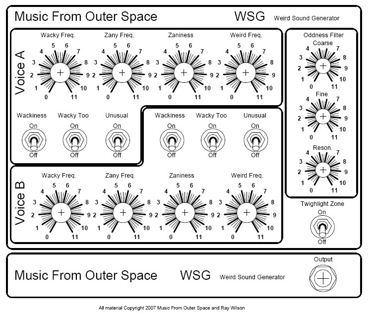
Give your Wacky, Zany, Weird, Odd Sound Generator that "Professional" look
There Are Two Panel Styles in Production
| Panel Type 1 - 8.5" x 6" x 1/16" | Panel Type 2 - 8.5" x 6" x 1/16" |
|
|
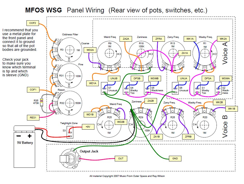
Panel Type 1 Wiring Diagram
View as PDF
Panel Type 1 Legend Template
View as PDF
Panel Type 2 Wiring Diagram
View as PDF
Panel Type 2 Legend Template
View as PDF
Making Your Own Panel and Case
Why Use Metal For The Panel..? I recommend using a metal front plate for the pots and switches so that by connecting it to the ground of the unit (battery negative - NOT EARTH GROUND) the pot bodies get grounded since they are in direct contact with the front plate. The ground I show in the panel diagram "Connect Chassis to Ground" is just a piece of tin plated ferrous metal (solderable) that is bolted to the metallic front panel. You can't solder to aluminum. You can buy these at Radio Shack and other electronics stores.If you don't use metal for your front panel then I suggest you line the inner surface with aluminum tape used by the heating and cooling people. When the adhesive side of this tape is stuck to the non-adhesive side (as when you cover a large area with several pieces and overlap them) the pieces conduct to one another very well. You do want to rub them down well and BE CAREFUL NOT TO CUT YOUR FINGERS as the edges can be sharp (wearing gloves is a good idea). Once they are connected my meter reads very low resistance between pieces (the same as when the leads are shorted). In my book that's pretty darn connected. You still want to bolt a solderable terminal to the front panel which is in contact with the aluminum (you can't solder to aluminum) and connect it to the circuit ground. Then you use an exacto knife to cut out the panel holes and mount your hardware. Voila... all of the pot bodies will be electrically connected to one another and to the circuit ground. I use 1/8" Masonite for prototype front panels and use the tape method to shield and ground the front panel components.
The reason you want to do this is because some points in the circuit are fairly high in impedance and the pot bodies can pick up and induce electromagnetic interference into the circuit and cause 60 cycle hum if they are not in contact with the circuit ground.
HOW TO MAKE A SIMPLE CASE FOR THE WSG
(These drawings are NOT for the panel sold above.)
 |
 |
 |
 |
 |
| View as PDF | View as PDF | View as PDF | View as PDF | View as PDF |
These diagrams show how to make the case and how to mount the PC board to the case. What you want to do in roughly this order is this:
- Make the parts of the case and paint it (if desired).
- (optional) Print out and laminate the front panel drawing at an office supply store.
- Print out the front panel, trim it and then glue it to the top of the case lined up with the holes.
- Cut holes in the overlay corresponding with the holes in the front panel.
- (optional) If you used non-conductive material for the front panel then use aluminum tape (usually found in the heating and cooling section of the hardware store) to laminate the inside of the front panel.
- Mount the components to the front panel (just poke them through the aluminum tape if you used it). If you did not use conductive material or aluminum tape I suggest you at least connect the pot bodies to ground. Maybe the sounds are even weirder without this... you be the judge.
- Do the intra-front panel wiring (kit buyers... be frugal with the wire as 24 feet goes quicker than you think).
- Populate the PC board with components.
- Lay the top up-side down to the side of the case (as if you had opened the case to the side) and the PC board near where it will be mounted and run the wires from the front panel components to the PC board keeping in mind that you will want to fold up the wiring when you are ready to attach the PC board to the bottom of the case and close it. (again kit buyers... be frugal with the wire as 24 feet goes quicker than you think).
- Attach the battery.
- Connect the battery and make weird sounds until your heart is contented.
MFOS Weird Sound Generator Front Panel PDF
MFOS Slightly Less Weird Sound Generator Front Panel (for the serious among us) PDF GIF
| I recommend using an aluminum panel so that it can be attached to ground and thus ground all of the pot bodies. |
More Panels From Other Creative Builders
Helpful Hints From Kit Builders
MFOS Weird Sound Generator Back Panel PDF
Kit buyers! Your kit contains SPDT (single pole double throw) switches. Simply use the bottom two terminals as shown below. You will leave the top terminal un-connected since you will be using the switch as if it was a SPST (single pole single throw). See this article for more info: MFOS Switches 101
Click here to find out how.
Kits come with SPDT switches which work perfectly as SPST
I send all Single Pole Double Throw Switches in kits because they also serve perfectly as SPST switches. As you can see in this image the switch has three terminals. The middle terminal is common and is connected to either of the outer terminals depending on the position of the switch bat. The terminal that is opposite of the way the switch bat leans is the terminal in contact with the middle terminal. Either outer terminal can be used.
Battery Snaps
We ship two types of battery snap. One has red and black wire (type 1) and one has two black wires with one of them imprinted with a white broken stripe (type 2). With the red and black type the red is the positive connection. With the two black wire type the one imprinted with a white broken stripe is the positive connection.
The type 2 snap (two black wire) has "zip" wire which can be separated easily by simply pulling the two wires apart near the stripped end.
Type 1 and 2 battery snaps. |
Type 2 zip wire separated. |
|---|---|
 |
 |
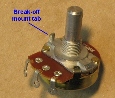
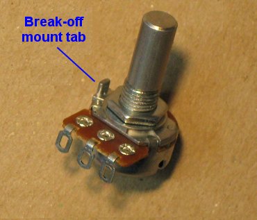
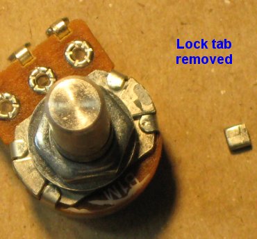
How To Remove Break-off Lock Tabs From Your Potentiometers
If your pots have little tabs on them you will need to remove them so that you can mount them to your faceplate. It is really easy to do. Carefully snap off the little tab near the pot body and voila it's done. Some kits come with larger pots and some kits come with smaller pots. The smaller pots are at times more expensive than the larger pots. They're all good quality pots and they all work the same way.
Regular Sized Pots |
Smaller Sized Pots |
|---|---|
| This is the break-off lock tab which can be used to keep the pot from turning when you turn the pot shaft but tightening the mounting nut works just fine. If you have the wherewithal to drill little holes for these pesky things... be my guest. If not... read on. | |
 |
 |
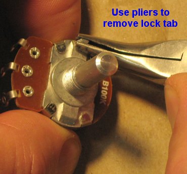
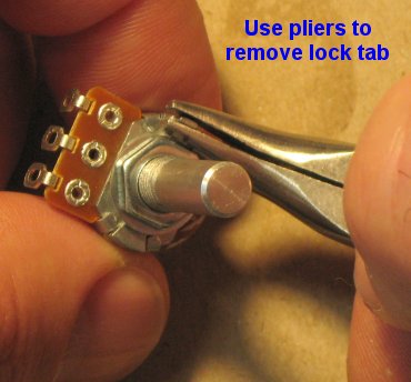
| Using pliers, grasp the tab as low on it as you can and then gently twist the pliers outward. I told you it was easy. | |
 |
 |
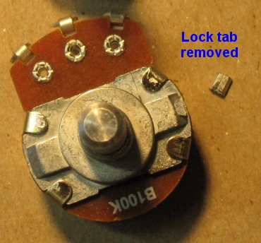
| The little broken off tabs look like this. Now you can mount your pot without the little tab getting in the way. | |
 |
 |