Ray Wilson authored this content while he was actively running MFOS as the founder and resident genius.
We retain the content because it reflects a valuable point of view representing that time and place.
Article by Ray Wilson
Features
IntroductionTired of buying batteries for your synth-diy projects. Buildthis wall wart supply and kiss batteries goodbye. Simple and versatile this board will power your projects in style.
!!! IMPORTANT SAFETY CONSIDERATIONS !!!
|

|
Some AC Wall Wart Sources
I thought my answer might be useful to anyone interested in this or any synth diy project that requires a DUAL supply. And yes... most do.
Power supply indicators on schematics generally appear as a circle or dot with the voltage expected at that point written next to it. When you see different power supply indications on a schematic (+12V, -12V, 5V, Ground, etc) that's how you know the number of voltage sources necessary for the circuit to operate normally. NEVER BUILD A CIRCUIT WITHOUT READING AND UNDERSTANDING THE SCHEMATIC FIRST. Circuits can require one, two, three, four... (I'll stop here but the list goes on) voltage sources. If you've ever removed a power supply from a computer you'll see outputs for even more than four voltages most of the time.
The majority of MFOS projects need a bipolar, dual or split power supply. The terms "dual", "bipolar" and "split" all imply two. The main point I'm trying to get across is that you cannot power a circuit that requires TWO voltage sources with ONE side of a single supply. In essence a dual supply is like having two DC supplies that are connected as follows: DC Supply A's negative pole is connected to DC Supply B's positive pole (this junction will become the signal/circuit ground). DC supply A's positive pole becomes the positive side of the dual supply. DC supply B's negative pole becomes the negative side of the dual supply. To reemphasize - the junction of DC Supply A's negative pole and DC Supply B's positive pole becomes the common ground (also called signal ground). Here is a picture to help cement the concept.
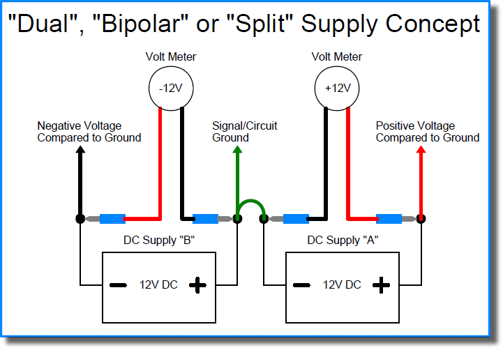
Both the MFOS "Adjustable LM317/LM337 1.5A Supply" and the MFOS "Wall Wart Power Supply" provide TWO voltage outputs AND ground. One output is positive in relation to ground and the other is negative in relation to ground. NEVER FEED A CIRCUIT THAT REQUIRES BIPOLAR POWER BY USING A SINGLE DC WALL WART EVER. You also NEVER CONNECT A DC OUTPUT WALL WART SUPPLY TO THE MFOS "Wall Wart Power Supply" it requires an AC Output Wall Wart. That's because in order to generate positive and negative voltage we take the AC output of the wall wart and rectify it with diodes so that positive voltage gets stored on the caps that serve the positive voltage regulator (LM78XX) and negative voltage gets stored on the caps that serve the negative voltage regulator (LM79XX). You only need ONE of either MFOS supply to power your synth-diy project because both of them provide the positive, negative, and ground outputs you need.
I get emails from people who somehow got the impression that one can just connect the -V terminal on a PC board to ground and that all will be well. It absolutely won't be. You have just shorted one end of the PC board's power supply to ground which will change the behavior of the circuit dramatically as in... it won't work at all. I get emails from people with pictures where they are attempting to use a DC wall wart to power a project that requires a DUAL, BIPOLAR, or SPLIT power supply. Others connect the MFOS "Wall Wart Power Supply" to a DC output wall wart then wonder why they are only getting voltage from one side of the MFOS "Wall Wart Power Supply" outputs.
I can't emphasize enough that if you don't read the circuit descriptions and understand the schematics then you are building blind which is not the most productive way to go. Reading and studying electronics text books and experimenting on simple circuits when you are just getting started will serve you very well. You will make faster progress with less frustration. I feel the frustration of people who want to build something cool but then get dissapointed after they have spent time, effort, and money and then didn't get the return on investment they were hoping for because they weren't adequately prepared for the project. I guess this comes off like a Dennis Miller rant but my main goal is to help you complete your projects successfully.
Cheers
Ray
"I have a question about the Wall Wart PSU. I don't see any information here about how much current this circuit can safely draw, nor anything about recommended heatsinking on the project page for this. DO you have any further information regarding these important points?"
I thought my answer might be useful to anyone interested in this project.
The current that can be safely drawn from a power supply that uses one of the wall-wart PCBs is based on several factors:
The current capacity of the wall wart. They come in many current capacities. I recommend that you do not use a wall wart that supplies greater than 1000 mA. It is for eliminating batteries and so should be used to provide similar currents however it can provide the capacity to run several synth modules as long as the wall wart in combination with the selected regulator can provide clean power. The page explains that the output voltage of the supply will depend on the selected regulator pair (e.g. LM7805/7905, LM7809/LM7909, LM7812/LM7912, LM7815/LM7915)
The output voltage of the wall wart. Wall warts come in a variety of output voltages IT IS VERY IMPORTANT TO USE AN AC OUTPUT WALL WART. So lets say the wall wart outputs 15VAC. Typically the VAC value of a transformer is it's RMS value. I'm thinking that the transformer manufacturers thought Volts AC was a little more marketable than Root Mean Square (RMS). So a 15VAC transformer puts out a peak voltage of 15 * 1.414V or 21.21V. If you were viewing the output on an oscilloscope you would see a sine wave (50 or 60 hz. depending on your locale) that had positive and negative excursions of 21.21V peak. This value when rectified and filtered by the diodes and capacitors in the wall wart will be capable of supplying voltage to any of the regulators mentioned above. The spec for the LM78XX/LM79XX series of regulators says that the input voltage should not exceed 35/-35 volts respectively so keep that in mind when buying your wall wart.
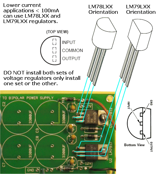
The current capacity of the voltage regulators used. Voltage regulators vary in their current ratings. The LM78XX and their corresponding negative partner regulators (LM79XX) claim to provide up to 1A of current. If you use them with a 500mA wall wart you should only expect to draw up to about 400 mA from the supply. If you try to draw more current you will begin to get ripple and degraded regulator performance and the wall wart could become warm and even fail. The LM78LXX (and LM79LXX) regulators can provide up to 100 mA. If you use a higher capacity wall wart and a regulator that can provide more current you can draw more current from the supply without degraded performance.
Heat sinks can be applied but they should not be shorted to one another or anything else. If you can find a heat sink that fits on the board without causing a short between the two regulators great! Otherwise you would need to fashion your own heat sinks from Aluminum L-channel usually found at a hardware store. It is usually sold in 3 to 8 foot lengths. Since you will only use 3/4" inches at a time you will have a lifetime supply for about 4 to 10 bucks. The metal tab on the 78XX series is at ground potential but the metal tab on the 79XX series is at -V potential thus shorting the heatsinks to each other (or ground in the case of the LM79XX will cause sparks and burned out regulators).
I hope this is helpful information but I recommend that if you have not built power supplies before that you buy a pre-made unit rather than try to build one. Most of us DIYers have burned out our share of regulators, cooked a couple of wall warts and seen the results of connecting electrolytic caps backwards. It's a jungle on the workbench and not for the faint of heart. I believe the page provides more than enough information for someone who has built power supplies before and is the reason I put the following information at the top of the page in bold letters:
"This is an advanced project and I do not recommend it as a first project if you are just getting started in synths or electronics. Only the circuit and some explanation are shown here. A lot of project building experience and electronics knowledge and equipment ownership (scope, meters, etc.) is taken for granted. If you are interested in building this project please read the entire page before ordering PC boards to ensure that the information provided is thorough enough for you to complete the project successfully."
If you are just getting started in electronics I wish you success and hope you keep going and gain experience and knowledge and come to enjoy the hobby as much as we nutty DIYers do.
Cheers
Ray
|
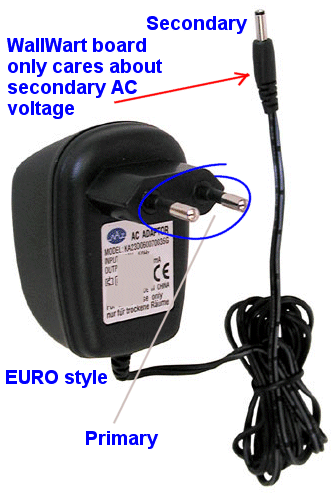
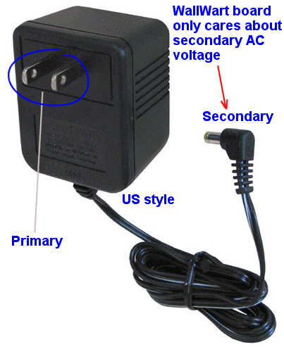
Does it matter if I use a EURO style wall wart? As long as the secondary voltage of the Wall Wart is correct (9 to 12 VAC... NOT DC) you can use a EURO or US type wall wart. The MFOS Wall Wart board does not care if the primary input is EURO or US it will work fine with either.
|
 |
 |
|
|
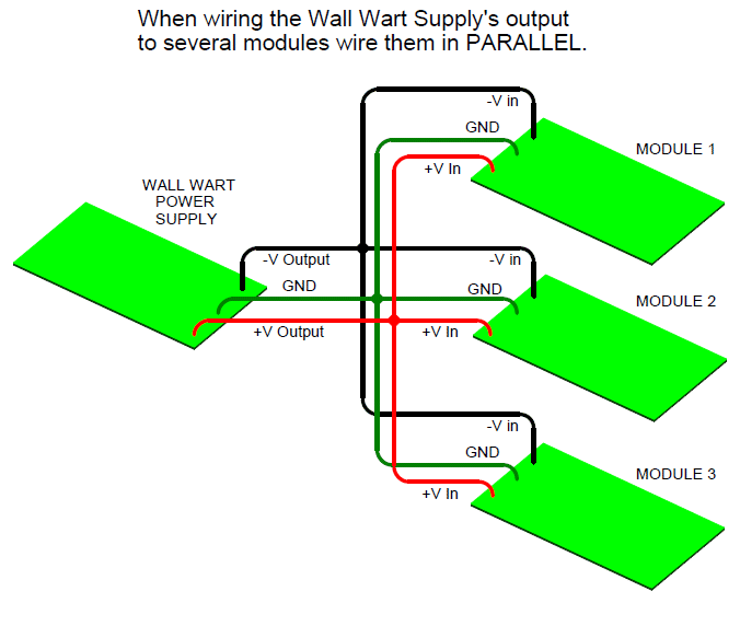
Wiring Multiple Modules to One Wall Wart Supply Depending on which size capacitors and what regulators you use (78XX/79XX or 78LXX/79LXX) you can wire more or less modules to the outputs of a MFOS Wall Wart supply. Read the entire page to get an idea of what I'm talking about. When you wire multiple modules to one power supply (and this goes for any power supply) wire them in parallel. That means that: the +V inputs of the modules all get tied to the +V output of the supply, the -V inputs of the modules all get tied to the -V output of the supply, and the ground inputs all get tied to the ground connection of the supply. Each module draws the current it needs from the supply. If you connect too many modules to a supply they will not be able to get the current they need from the supply and performance will suffer. That is why each module on MFOS has info about the current consumption for that module. Remember that 78LXX/79LXX regulators supply about 100 mA max and that 78XX/79XX regulators supply about ten times that (or 1000 mA). When multiple modules are connected their current consumptions add up. For example: three modules that consume 30mA each connected to the supply will consume a total of 90mA. |
 |
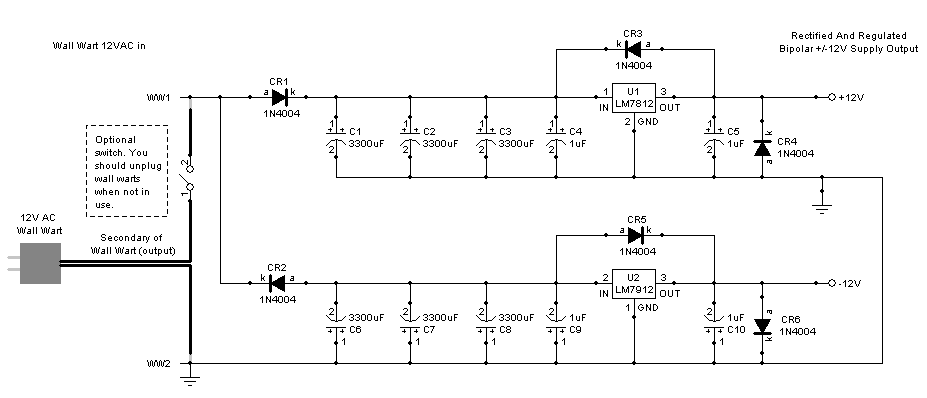
Wall Wart Power Supply Schematic Page 1 (June 2010 Version Added Load R's) PDF
The load resistors were added as a convenience for testing without a load and are not necessary. The negative regulator needs a slight load to begin regulating which is normally provided by the circuit being powered. These resistors provide a small load so the output voltage can be observed prior to connecting the supply to your circuit.

Wall Wart Power Supply Schematic Page 1 (Original Version for Reference) PDF
|
This supply uses half way rectification to produce a positive and negative DC voltage with respect to the WW2 (wall wart 2) connection. Just so you know there is no 1 or 2 as far as wall wart secondaries are concerned but be aware that one side of the output is going to be used for ground (as shown in the schematic) and you do not want to short that to the other output. How could you do that? Well if you use a wall wart jack and plug when you install your wall wart supply in a case be aware that if the plug exposes either wire of the wall wart secondary to any metal involved in mounting the plug then be sure you use that side of the wall wart secondary for your ground (WW2 connection). So in case the wall wart secondary plug mounting contacts your circuit's ground you don't short the wall wart secondary. You might just want to mount the wall wart plug (if you use one) to non-conductive material like plastic or wood. If you don't have any idea what I'm talking about here don't build this so you don't shock yourself, burn up the wall wart, or experience any other untoward event. Diodes CR3, CR4 and CR5, CR6 are protection diodes recommended in National Semiconductor Application Note AN-182 for protecting three terminal regulators from unwanted current paths that the output capacitors can inadvertently cause under certain conditions. Although the ones for the negative regulator are not considered as critical, better safe than sorry I always say. The 1uF tantalums close to the regulator pins are also recommended by National Semiconductor for operational stability. |
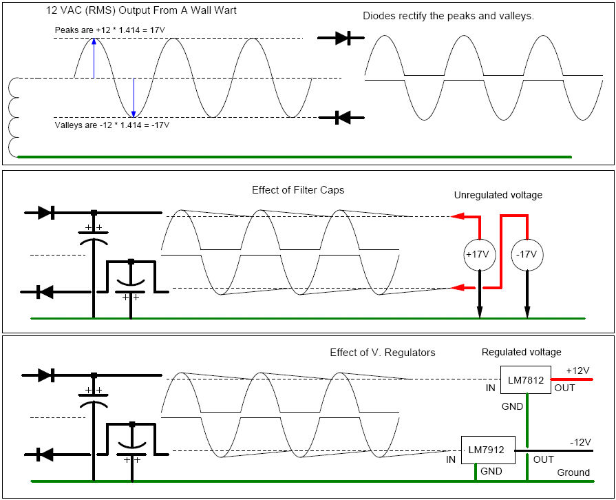
Wall Wart Power Supply Theory PDF
|
As the diagram shows if you look at the output of a wall wart with a scope you see that the output voltage goes positive and negative with respect to the side you connected to the scope ground. For our 12VAC wall wart the voltage goes about 17V positive and -17V negative (in practice the voltage was actually a bit higher). Rectifier CR1 steers the positive excursions onto the filter caps (caps C1, C2, and C3 in parallel actually just make one bigger cap) and rectifier CR2 steers the negative excursions on the filter caps (C6,C7 and C8). The rectified and filtered positive voltage on C1,C2 and C3 is fed into voltage regulator U1 (LM7812 +12V Voltage Regulator) and the rectified and filtered negative voltage on C6,C7 and C8 is fed into voltage regulator U2 (LM7912 -12V Voltage Regulator). The outputs of the voltage regulators provide... drum roll... regulated voltages. If you know what you're doing you can see that you could use different wall wart voltages (9VAC, 12VAC or 15VAC) and different regulators (see the table) to get different regulated output voltages. I use +/-12 and thus the schematic shows that setup. |
| Desired Voltages | Higher Currents U1/U2 | Lower Current U1/U2 | Wall Wart Output |
| +/-9V | LM7809/LM7909 | LM78L09/LM79L09 | 9 VAC Output |
| +/-12V | LM7812/LM7912 | LM78L12/LM79L12 | 12 VAC Output |
| +/-15V | LM7815/LM7915 | LM78L15/LM79L15 | 15 VAC Output |
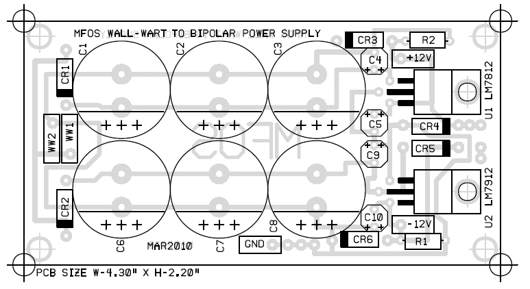
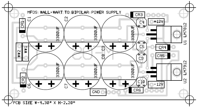
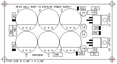
Wall Wart Power Supply PCB Parts Layout (June 2010 Version Added Load R's) (Parts Side Shown) PDF
Notice You do not have to add all of the large electrolytic filter caps if your application draws low current. One set of caps worked fine for my Sound Lab.
Wall Wart Power Supply PCB Parts Layout (Parts Side Shown) (Original Version for Reference) PDF
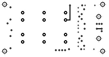
Wall Wart Power Supply PCB Bottom Copper (Parts Side Shown)
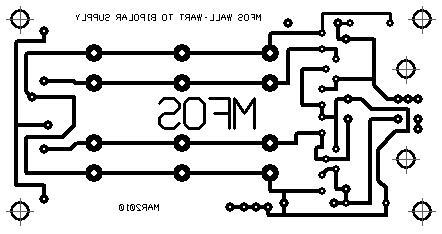
Wall Wart Power Supply PCB Top Copper(Parts Side Shown)
Wall Wart Power Supply PCB Top Silk Screen
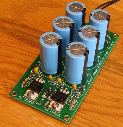
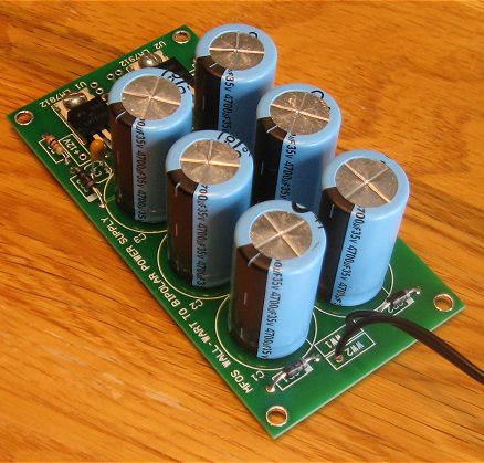
Wall Wart Power Supply PCB Populated
140-XRL35V3300-RC 3300 uF (18 x 36) mm with 7.5 mm lead spacing.
140-XRL35V4700-RC 4700 uF (18 x 36) mm with 7.5 mm lead spacing.
PLEASE NOTE! Currently shipping PC boards do have the '+' symbols screened on. Older PC boards do not have the '+' symbols silk-screened on them but the plus side of the electrolytic caps go on the side with the line (as if they did have the plus symbols shown in the parts layout).
Also note that you do not have to add all of the large electrolytic filter caps if your application draws low current. One set of caps worked fine for my Sound Lab.
 |
 |
Wall Wart Power Supply PCB Using Low Power Regulators
Wall Wart Power Supply Project Parts List
| Qty. | Description | Value | Designators |
|---|---|---|---|
| 1 | LM7812 +12V Voltage Regulator | LM7812 | U1 |
| 1 | LM7912 Voltage Regulator | LM7912 | U2 |
| 2 | Resistor 1/4 Watt 5% | 2.4K | R1, R2 |
| 6 | 1N4004 General Purpose Rectifier | 1N4004 | CR1, CR2, CR3, CR6, CR4, CR5 |
| 6 | Capacitor Electrolytic | 3300uF | C1, C2, C3, C6, C7, C8 |
| 4 | Tantalum Electro (35V) | 1uF | C4, C5, C9, C10 |
| 1 | 9 to 12 VAC Output Wall Wart | 12VAC Output | |
| 1 | Optional SPST Switch | SPST |