Ray Wilson authored this content while he was actively running MFOS as the founder and resident genius.
We retain the content because it reflects a valuable point of view representing that time and place.
Article by Ray Wilson
Features
IntroductionA vocoder has got to be one of the coolest signal processors going. It allows you to impress vocal harmonic and dynamic characteristics onto other sound sources making them sound as if they are talking. This vocoder design works by using one lo-pass filter (100 Hz.), ten successively tuned band-pass filters (154, 208, 285, 395, 542, 720, 1013, 1495, 2000, 2546 Hz.) and one hi-pass filter (3330 Hz.) to separate the incoming control signal into its harmonic constituents. For each band the control signal appearing at the output of its corresponding filter is full wave rectified and low pass filtered to obtain the control signal's envelope voltage. This signal is used to drive a VCA through which the channel's filtered audio is amplitude controlled. The whole circuit is described below but all I can say is that this thing is totally cool and I'm very happy with mine (I am somewhat biased). |
|
User Modifications
I have a good feeling about this project. It's my hope that it becomes one of those that people enjoy building and it's perfect for people who enjoy modifying designs (see Vocoder Expansion and the Filter Design tab). If and when I ever modify mine (who knows, winter's coming...) I'll document it completely in a new sub-tab entitled "Modifications". Any experimenters willing to share schematics/photos of discovered improvements or modifications are invited to let me know at info@musicfromouter...(you know the rest).com. Please include links to sound samples when you email so I can publish them along with the modification information. People will appreciate hearing what the mod results in. As a standard for at least one of the samples (and I suggest you provide several sample links) I propose using one of the sample vocal loops below so everyone knows what the voice control source material sounds like. I'll add the info (or links to it if you prefer) and sound sample links to the "Modifications" page with credit to you for having contributed the idea. Open source comes to vocoders!
Sample MP3s
I really hope you take the time to listen to the samples before embarking on this project. It is a fairly large investment in time and money and I want you to be happy with the results. I am looking forward to using mine in some of my upcoming musical projects and I really like it. The samples will give you a good idea of the speech intelligibility you can expect when used with a decent microphone and a keyboard. Your build will sound similar.You should also know that a twelve channel vocoder is not going to sound like a DSP plugin or footpedal vocoder. So... before you get out your solder iron expecting one thing... listen to the samples. I love this vocoder and I think it's totally cool but it's kind of like my child by now so you can understand why. If you do build the project I have to say that the board soldered up very nicely and the vocoder worked prefectly after I tracked down one unsoldered resistor lead and calibrated the channel gains. Good soldering.
babadaboopbadubadooda-Track 7.mp3
bigband-Track 5.mp3
bigstringsgoing-Track 6.mp3
bigswell-Track 2.mp3
dynamicrange-Track 4.mp3
epowerbiggs-Track 3.mp3
gottadothat-Track 15.mp3
hardsync-Track 3.mp3
harmonica-Track 9.mp3
hellotherestrings-Track 5.mp3
internaloscillator-Track 1.mp3
moreskat-Track 9.mp3
musette-Track 8.mp3
pianostringswhitenoise-Track 5.mp3
pianovoice-Track 2.mp3
skat-Track 3.mp3
solarflare-Track 14.mp3
stringrobot-Track 2.mp3
trumpetandboneswhitenoise-Track 5.mp3
vocoder calibration wave.mp3
vocodersample001-Track 2.mp3
worldofpeace-Track 11.mp3
worldofpeaceii-Track 12.mp3
Table of Contents
Schematics Calibration - Setting Filter Band Gains PC Board Information Front Panel Information Parts List (BOM)
Introduction - Continued
This vocoder design works by using one lo-pass filter (100 Hz.), ten successively tuned band-pass filters (154, 208, 285, 395, 542, 720, 1013, 1495, 2000, 2546 Hz.) and one hi-pass filter (3330 Hz.) to separate the incoming control signal into its harmonic constituents. For each band the control signal appearing at the output of its corresponding filter is full wave rectified and low pass filtered to obtain the control signal's envelope voltage.
Meanwhile the audio (signal to be modified) path is also going through a separate but identical set of twelve filters. The output of each of these filters goes through a VCA that is controlled by the envelope follower output of the corresponding filtered control signal's envelope voltage. Thus when there is harmonic content contained in a band of the control signal a proportional amount of the same harmonic content of the audio signal is passed through it's filter and VCA to the output of the vocoder.
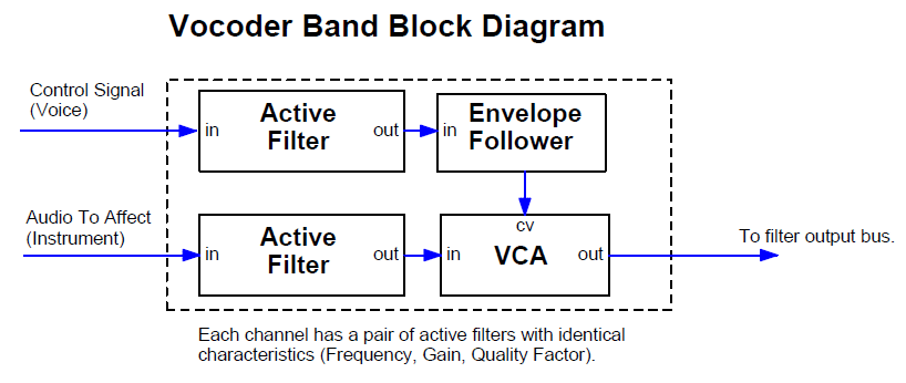
The Vocoder Band Block Diagram shows that each band consists of two identical active filters, an envelope follower and a VCA. The control signal's active filter output feeds an envelope follower whose output voltage controls the VCA. The VCA controls the amplitude of the channel's audio filter output. Thus whenever the control signal contains harmonic content within the pass-band of it's particular filter it turns the VCA on causing the audio signal filtered with the same filter characteristics to be output to the mix bus.
The MFOS 12 Channel Vocoder Block Diagram shows how 12 of these channels, each tuned to a separate band of frequencies are routed to the main output bus. You may have heard one of those guitar effects in which a speaker drives sound into a plastic tube that the musician places in his/her mouth. In that case the musician uses his/her mouth to apply the same physical filtering to the guitar sound coming through the tube as is normally applied to the sound emanating from the musician's vocal cords. The result is that the musician can make the guitar 'talk'.
In a way the vocoder applies similar filtering to the audio signal but uses a more round about way to get there. The audio signal is routed through the lo-pass filter, ten bandpass filters and the hi-pass filter which are controlled by the VCAs. The audio signal path's VCAs and filters are the analog of the mouth's ability to apply acoustic filtering. The amount of each filter's output is directly proportional to the harmonic content contained in the control signal (voice).
The internal oscillator and noise source provide ready-to-go audio signals to experiment with. The white noise, with level adjustment, is also applied to the hi-pass filter's VCA input so that when high frequencies are present white noise is emitted. I did not employ the 'sibilance detect' circuit found in some designs that compare the energy in the lower bands to the energy in the upper bands to see if white noise should be emitted I just let it fly when frequencies above 3330 Hz. are detected. I call my method the poor man's sibilance detector and it seems to work just fine.
You can mix the raw control or audio signals into the output via the Control Mix-In and Audio Mix-In controls. You can select white or pink noise as well as the internal rectangle wave oscillator to be applied to the vocoder input. Using noise as the audio signal creates odd whisper effects and applying the internal oscillator makes you sound like a robot. The output level control adjusts the amount of the unit's signal that is fed to your amp or mixing board.
Use a good quality mic for best results
In the just so you know category: using a quality microphone with a flat frequency response between about 70 to 10,000 Hz. (or better) will result in the best speech intelligibility. Using a low quality mic will be a very disappointing experience. I use my Octava capsule mic into my mix board and then take the output of the channel via the insert jack. Just insert the tip (send) jack's output to the vocoder's Control (voice) input. On most mixers when the stereo-tipped insert plug is in a channel's insert jack the mic is effectively cut off from the rest of the mixer (unless you plug through an effect of some kind). The insert jack is switched such that it expects me to "insert" something and since the insert cable plug to route the signal back onto the mixer's bus is not connected the channel's pre-amp is not connected to the mixer's audio bus.
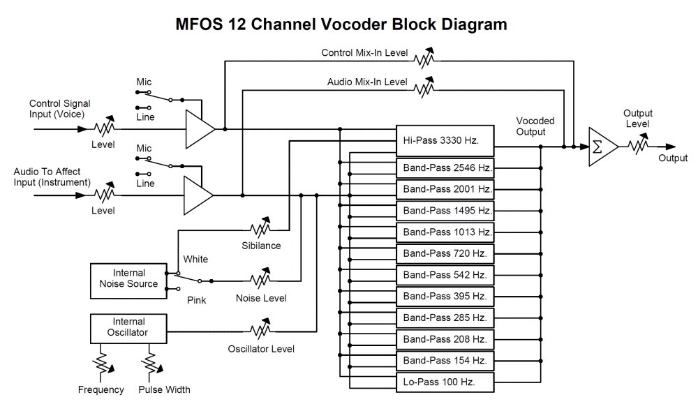
Table 1 presents the characteristics of the filters used in the MFOS vocoder's bands.
Table 1 - Frequency Characteristics of MFOS Vocoder Filters
| Frequency | Type *MFB = Multiple Feedback | Gain | Q |
| 3330 | MFB* Hi-Pass | -2.13 | .88 |
| 2546 | MFB* Band-Pass | -2.8 | 4.48 |
| 2001 | MFB* Band-Pass | -3.15 | 5.16 |
| 1495 | MFB* Band-Pass | -3.4 | 3.2 |
| 1013 | MFB* Band-Pass | -2.8 | 3.9 |
| 720 | MFB* Band-Pass | -2.8 | 3.7 |
| 542 | MFB* Band-Pass | -3.12 | 3.75 |
| 395 | MFB* Band-Pass | -2.5 | 3.7 |
| 285 | MFB* Band-Pass | -3 | 3.55 |
| 208 | MFB* Band-Pass | -2.4 | 4 |
| 154 | MFB* Band-Pass | -2.4 | 2.96 |
| 101 | MFB* Lo-Pass | -2.55 | .55 |
With A Little Help From My Friends...
I looked all over the web to find vocoder designs to learn from. I did not copy anyone's design but got some great ideas and basic principles from these sources. I invite you check them out and learn more about vocoders.
- PAIA Vocoder - Craig Anderton
- Vocal Harmonizer and Vocoder - Philip Decamp, Uriel Klieger, Andrew McPherson
- Okita Vocoder Documentation - N. Okita
- ETI Vocoder Documentation - Richard Becker
Designing filters is hard unless you find cool tools on the web that are freely available. Here are some I found that helped me to succeed with this project.
MFOS Vocoder Schematics
Table of Contents
Vocoder Full Schematic
View as PDF
Vocoder Schematic Page 1
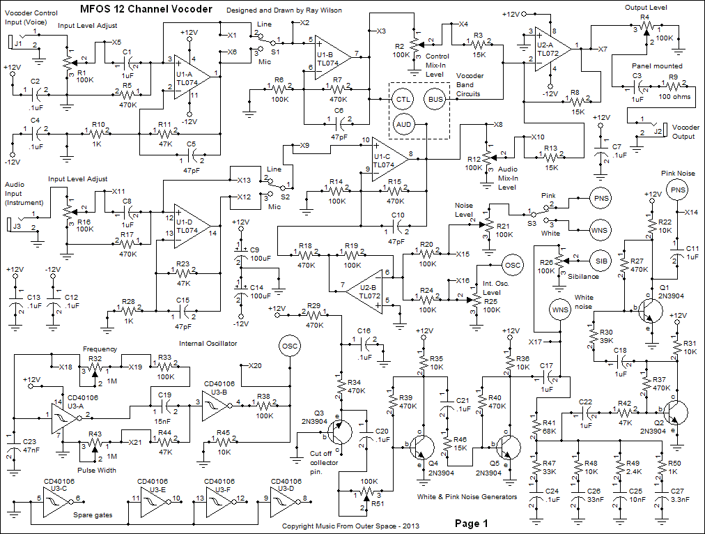
View as PDFPage one of the schematic encompasses a number of the housekeeping functions of the vocoder. U1 (TL074CN) is used to buffer both the control signal (voice) and the audio signal (instrument). Both inputs work in a similar manner so I will only describe the Vocoder Control Input. The Vocoder Control Input jack's tip is connected to Input Level Adjust pot R1 (100K linear taper). The signal picked off of R1's wiper is applied to the non-inverting input of buffer U1-A via C1 (1uF non-polar cap). U1-A applies a gain of 48 (thanks to feedback resistor R11, 47K and R10, 1K to ground) to the adjusted input signal. The 47pF cap across U1-A's feedback resistor mitigates any penchant the op amp may have to oscillate due to its high gain. Switch S1 selects between the output of U1-A or the unamplified signal dropped on R5 (470K resistor). Switch S1's center pole applies the input signal (with or without gain) to the non-inverting input of buffer U1-B (TL074CN). Again C6 (47pF cap) keeps U1-B quiet oscillation-wise. U1-B applies a gain of 5.7 to the signal appearing at it's non-inverting input. Together U1-A and U1-B can apply a maximum gain of 273 to a signal applied to the Vocoder Control Input provided that switch S1 is in Mic position. The output of buffer U1-B feeds both the CTL bus, which applies the control signal to the control signal path's bandpass filter inputs, and the Control Mix-In Level pot. The Control Mix-In Level pot allows the control signal to augment the vocoded signal. When you sing in unison with the instrument you are impressing vocal harmonics on you can allow some of the control signal (voice) to come through to the output. This can help with intelligibility or just be used to provide a cool effect. Expected input levels for line are in the 1V to 5V P-P range and can be attenuated with the Input Level pots. When set to Mic as stated before a possible gain of 273 can be applied to the signal. The input impedance is roughly 100K. The output at pin 7 of U1-B when input levels are set correctly will be about +/-3V to +/-5V Peak to peak (the same is true for the audio signal level seen at pin 8 of U1-B). The output level signal you should expect is between +/-1V to +/-5V depending on input levels.
Circles with letters in them are off-page connector symbols. Consider all circled points with the same token to be connected together on the same schematic page and across separate schematic pages.
The Audio Input path functions similarly using U1-D and U1-C. The output of U1-C (Audio Input path buffer) is applied to both the AUD bus, which applies the audio signal to the audio signal path's bandpass filter inputs, and the Audio Mix-In Level pot. You can apply a portion of the Audio Signal to the output if desired. Doing so allows both the vocoded audio and the raw audio to be mixed to the output. U2-A (1/2 TL072CN) is the vocoder's output buffer. All of the vocoder's band pass channels feed the inverting input of U2-A which acts as the circuit's main mixer. U2-A's output is fed to Output Level pot R4 whose wiper feeds the output jack via 1uF non-polarized cap C3 in series with 100 ohm resistor R9. NOTE: C3 (1uF bipolar cap) and R9 (100 ohm resistor) are not located on the circuit board but are installed on the unit's front panel.
U3 is used to provide a relatively low frequency square/pulse wave generator to apply to the unit's audio path. Using the unit's internal oscillator set to a low frequency can make you sound like a robot. The frequency of the oscillator is determined by the setting of frequency pot R32 (1M linear pot) and the values of R33 (100K resistor) and C23 (47nF cap). The range of the internal oscillator is from about 20 Hz. to 240 Hz. and the width can be varied over a nice usable range (especially so at lower frequencies). You can change the range of oscillation by making R33 lower in value (oscillator range will go higher in frequency) or making C23 higher (lower overall range) or lower (higher overall range). The output of the oscillator is attenuated by a factor 0f 10 by resistive divider (R38 100K and R45 10K). That lower level signal is applied to Internal Oscillator Level pot R25. R25's wiper is connected via R20 (100K resistor) to U2-B's inverting input. U2-B acts as an inverting mixer for the internal noise and oscillator signals which are applied to the non-inverting input of Audio path buffer U1-C via R18 (470K resistor). The width of the oscillator's square/pulse output is adjusted by R43 (1M pot). C19 (15nF cap) and R43 in series with R44 comprise a differentiator for the square wave appearing at the output of U3-A. The leading edge of the square wave from the output of U3-A is propagated through C19 to drop on R43 in series with R44. As the resistance between the input of U3-B and ground becomes lower by adjusting R43 the square wave is more and more differentiated, thus becoming narrower and narrower. U3-B squares up the differentiated pulses so that as the Pulse Width pot is adjusted the output of U3-B goes from a square wave to a fairly narrow pulse wave. The adjustment is designed to affect the width of the pulse most when the frequency is relatively low. When the internal oscillator is used and the Audio Mix-In pot is turned up the raw and vocoded signals experience phase cancellations that vary as the Audio Mix-In level is changed. Not sure who would use it this way but it sounds kind of cool.
The unit's white and pink noise generators are really old school. I decided to just use transistors for this and skip another op amp. Essentially we generate white noise using the reverse biased emitter base junction technique. Q3 is the 'noise' transistor and may need to be selected although I have found that this circuit seems to work with just about any 2N3904 I've used. The white noise appearing at Q3's emitter base junction is amplified by Q4 and Q5 and their associated biasing and coupling components (R39,R35,C21,R46,R40, and R36). The signal is gained up to a sufficient amplitude on the collector of Q5 and we couple it, via 1uF non-polar cap C17 to: 1) the WNS (White Noise) circuit point which goes to White/Pink noise selector switch S3, 2) to one end of the Sibilance adjust control and 3) to the input to the pink noise approximation filter R41 (68K). R47 through R50 and C24 through C27 provide a very rough pink noise filter. I buffer the 'pink' filtered noise with two stages of transistor amplification (Q2 and Q1 and associated components). I have provided a means to adjust the amplitude of the white noise via R51. Adjust it so that there is about 3V to 4V P-P of white noise seen at circuit point WNS. You should see about 3V to 4V P-P of pinkish noise at circuit point PNS. The white noise sounds like a hiss and the pink noise sounds more like a roar. If you need to adjust the level of the pink noise you can adjust the value of R30. Up for less pink noise amplitude and down (with a limit of about 10K) for more amplitude.
White or pink noise can be selected via S3 to be applied to the audio path of the unit. Noise Level pot R21 permits adjustment of the level. The vocoder sounds very interesting and unusual when vocal harmonics are impressed on white or pink noise.
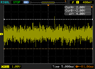
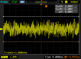
Schematic Page 1 Scope Photos
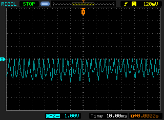
| White noise seen at the center terminal of S3 while set for White Noise. The switch is fed from circuit points X14 (Pink noise) and X17 (White noise). | Pink noise seen at the center terminal of S3 while set for Pink Noise. The switch is fed from circuit points X14 (Pink noise) and X17 (White noise). |
 |  |
The internal oscillator set for a narrow pulse-width. Note the level is about 1V P-P. The probe was on the internal oscillator level pot (R25) terminal which is fed by circuit point X20. |
Internal oscillator set for square wave width. The probe was on the internal oscillator level pot (R25) terminal which is fed by circuit point X20. |
 |  |
Vocoder Schematic Page 2
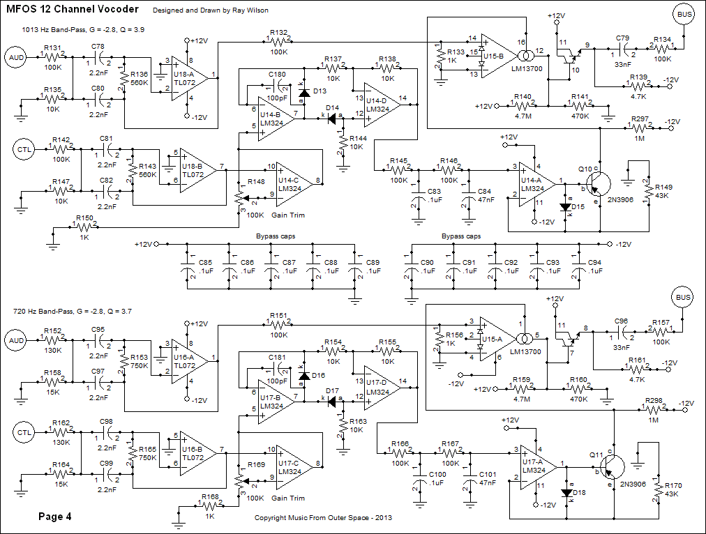
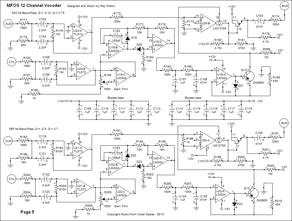
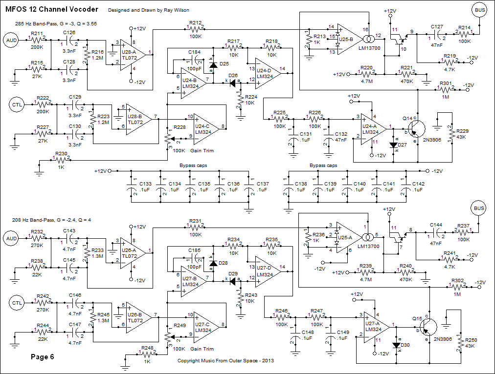
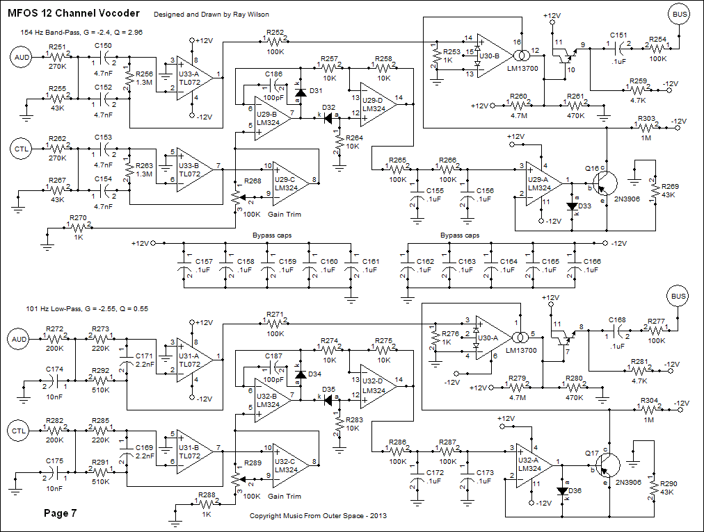
View as PDFI'm only going to describe the operation of the first channel because all of the channels work in exactly the same fashion. I'll call attention to components of the circuit that change value in the other frequency bands and why. All of the vocoder frequency band circuits start off with two identical filters. In the case of the first channel the filters are both multiple feedback high-pass filters (3330 Hz., G = -2.13, Q = .88). The next ten channels use multiple feedback band pass filters and the final channel uses a multiple feedback lo-pass filter (see Table 1).
The signal applied to the AUD circuit point is filtered by the 3330 Hz. multiple-feedback high pass filter built around U4-A (1/2 TL072CN) and associated components (C28,C29,R57,C31, and R58). IC U6-B (1/2 NJM13600N Dual Transconductance Op-amp) plays the role of VCA in this design. The filtered audio signal is applied to the non-inverting input of U6-B after being attenuated by resistive divider R52 (100K) and R55 (1K). It is important not to over-drive the transconductance op-amp's input to avoid distortion. I did not use a capacitor to couple the filter output to the input of the VCA because the filter's gain (and thus offset) is low. When current is applied to U6-B's amplifier bias input (pin 16) the signal is passed through U6-B and amplified a bit by the chip's on-board darlington pair. The on-board darlington pair is biased by R59 (4.7M) to +12V and R60 (470K) to ground so that the output signal operates about ground and has amplitude of about 6V P-P. In practice you will see as much as -250 mV of offset on the output of the VCAs but not to worry the offset is blocked by C30 10nF cap which couples the output of the VCA to the vocoder mixing bus via R56 (100K resistor). The caps coupling the signal from the output of the VCAs to the mixing bus in the various channels have different values depending on the channel's filter characteristics. Progressively lower frequency channels have progressively larger coupling caps (culminating in .1uF for the 100 Hz Lo-pass filter). C30 blocks any DC and/or low frequency VCA control voltage signals that bleed through to the VCA's output from getting to the main audio bus.
The signal applied to the CTL circuit point is also filtered by an identical 3330 Hz. high pass filter built around U4-B (1/2 TL072CN) and associated components (C32,C33,R65,C34, and R66). U4-B's output is connected to the non-inverting input of gain block U5-C. R67 changes the gain of U5-C over a range of from 1 to 100 and is used during calibration of the unit. (I'll explain calibration a bit later on). Components U5-B, U5-D, D1, D2 R54, R53 and R62 comprise the precision rectifier. Note: This configuration inverts the positive peaks and passes the negative peaks resulting in output of a negative full wave rectified signal. However, if you ever need a precision rectifier that outputs the positive peaks simply reverse the polarity of both diodes in the circuit.
The precision rectifier's output is fed to the input of the two stage low pass filter (100K resistors R63 and R64 and .1uF cap C35 and 22nF cap C36) buffered U5-A and is thus smoothed significantly. This filtered rectified voltage is the channel's proportional control voltage that will determine how much of this channel's audio material is passed through its VCA. U5-A (in conjunction with D3 (1N914 diode) and Q6 (2N3906 PNP transistor)) also functions as the channel's envelope voltage to current convertor which is applied to the VCA's bias current input (U6-B pin 16).
Note that the capacitors used in the envelope follower lo-pass filters of the other channels progressively increase in value as each channel's frequency band gets progressively lower.
IC U5-A is used as a voltage to current converter in conjunction with transistor Q6 (2N3906 PNP) and diode D3. When no signal is being fed into the vocoder's control signal input you can expect to see about -400mV to -500 mV at the output of U5-A. As voltage on the output of U5-A goes more negative more current is allowed to flow through R68 (43K) and the emitter to collector of Q6 resulting in current flowing into the bias input (pin 16) of U6-B. The greater the current the greater the amplitude of the signal passing through the VCA and vice versa. Thus the level of the control signal's harmonic content that is above 3330 Hz. will control the level of the similarly filtered audio signal permitted to pass through the VCA. Each band works in a similar fashion resulting in the audio signal mirroring the harmonic and dynamic content of the control signal. When all of the channel outputs are mixed together you get the same effect as the guitar-tube-mouth device. The voices dynamics and harmonics control the audio signal's dynamics and harmonics and voila your keyboard (or whatever audio input you insert) is talking.
Only the 3330 hi-pass channel has the sibilance (white noise) applied to it's VCA. When the VCA for the high pass filter is open, white noise is mixed with the signal from the audio path's hi-pass filter. I think this does a reasonable job of simulating the sssss sound as well as some hard consonants.
Bypass caps are everywhere in this circuit which is why you see about ten .1uF per caps schematic page. To reiterate the values that change in the other bands will be the filter component values, the envelope follower filter caps, and the VCA mix bus coupling caps. Everything else works pretty much the same.
All diodes are 1N914 or 1N4148 high speed switching diodes.

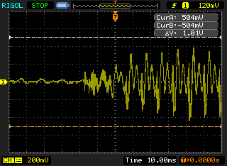
Schematic Page 2 Scope Photos
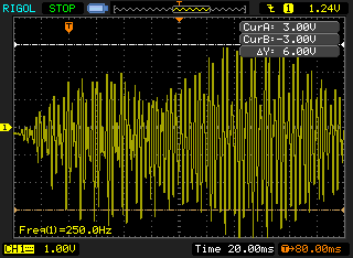
| The expected input is between about 1V and 5V P-P. Levels can, of course, be set with the Input Level pot. This photo is of the Vocoder Control input jack's tip terminal (on page 1). | With the expected input level fed in you should see typical output of your filters in the neighborhood of 5V P-P. This was taken at the output of U33-A (pin 1). | |
 |
 |
|
|
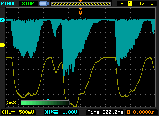
The output of one of the precision rectifiers. Notice that we rectify the voltage so as to obtain the negative going peaks. The amplitude will depend on the amplitude of the signal being fed to the precision rectifier. |
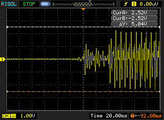
The rectified voltage in blue and the output of one of the envelope followers in yellow. You can see how the low pass filter smooths the signal allowing us to arrive at the envelope of the signal. The horizontal sweep is very slow which is why you can't discern the blue trace's excursions very well. |
This is the output of a typical VCA. The output has some offset (between -150mV to about -250mV) but this is blocked from the audio bus by a coupling cap on each band. You can see that the output can get as high as +/-3V or so. |
 |
 |
 |
Vocoder Schematic Page 3
View as PDFCircuit Description (See Vocoder Schematic Page 2)
Vocoder Schematic Page 4
View as PDFCircuit Description (See Vocoder Schematic Page 2)
Vocoder Schematic Page 5
View as PDFCircuit Description (See Vocoder Schematic Page 2)
Vocoder Schematic Page 6
View as PDFCircuit Description (See Vocoder Schematic Page 2)
Vocoder Schematic Page 7
View as PDFCircuit Description (See Vocoder Schematic Page 2). Additionally it should be noted that the last filter shown is a multiple-feedback Lo-Pass filter with a cutoff frequency of 100 HZ.
MFOS Vocoder Channel Gain Calibration
Table of ContentsWhen calibrating the vocoder it is essential that you use a wave file or MP3 of your voice to play through it as you work. It is just not possible to use a microphone and your ears because your voice is too loud in your head even with headphones on. Trust me on this. This is a sample of the type of file I use to calibrate but you can make one for yourself very easily. As a matter of fact it's probably best to 'tune' the vocoder to your voice during calibration. Right click either file and select "save target as" to download. The wav file is 14M the MP3 is about 2M but I suggest you use the non-compressed wav format if possible.
vocoder calibration wave.wavPlay the wave file on your computer (if your player allows set it for repeat play) and take the output of the computer's sound card and connect it to the Voice Control input of the vocoder. You can either use the internal oscillator and noise source as an audio source or connect a keyboard set to a sustaining patch. Preferably a sustaining patch with a lot of harmonic content like horns or bright strings. Connect the keyboard to the Audio Input and tape down a couple of keys a fifth or so apart so the audio signal is constantly present. Turn both input levels up to about 3/4 (less if your computer puts out a hot signal).
We will calibrate the 3330 Hz. hi-pass filter channel as an example. All of the channels are adjusted in the same manner.
Connect the output of the vocoder to an amplifier that you can listen to either in phones or speakers. The idea will be to connect one input of the scope to the output of the Vocoder Control input's filter output. For example when testing the 3330 Hz high pass circuit connect channel one to the output of U4-B (pin 7). This will be the high harmonic content of the Control input. Connect channel two to the output of the corresponding channel's VCA (pin 9 of U6-B).
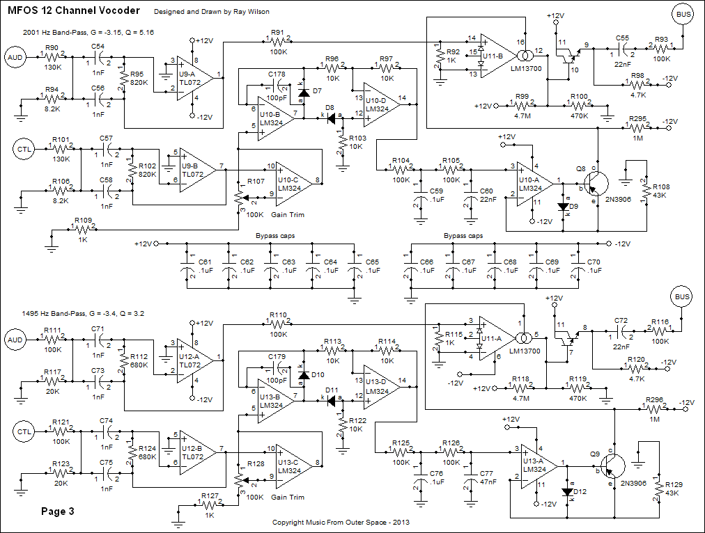
Set the scope to a slow sweep so you can clearly see peaks and valleys in the filtered Control input signal. For each channel we adjust we are going to compare what we see on channel one (the filtered voice control signal) to what we see on channel two (the channel's filtered output through the VCA). The image below shows what I mean. The amplitudes of the two channels correspond nicely.
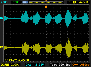
In order to get the two signals to correspond you need to adjust R67 (for the high pass filter) setting the gain of U5-C until the two signals share a similar envelope (like the image above).
Move from channel to channel adjusting the corresponding gain trimmer and make sure you move both probes every time you change channels so you don't get confused and adjust the wrong channel's gain. Who in the world would do that you may wonder... Let's just say it can happen. Once the levels are adjusted properly you should start to be able to discern the words on the test WAV file or MP3 more clearly. Try several different synth patches for the audio input as some will be more intelligible than others. Add some white or pink noise to the mix to gain intelligibility. Add sibilance to the mix to bring out the sibilant consonants. Experiment - Have fun!
PC Board Information
Table of Contents
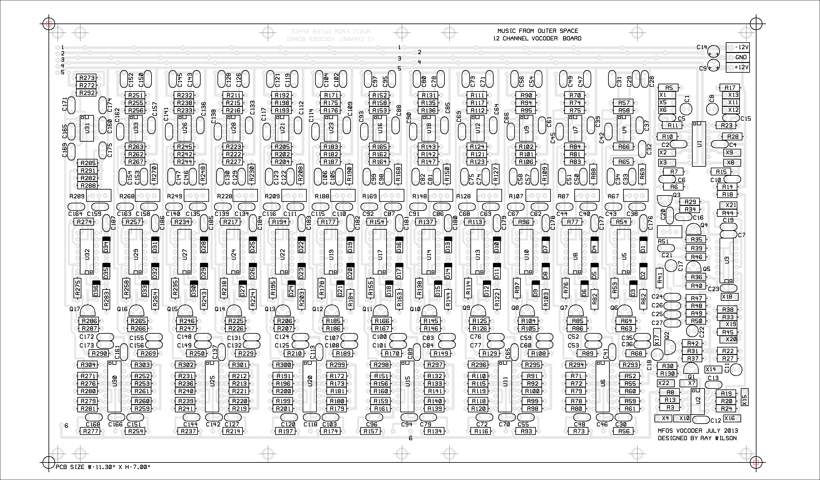
Vocoder PCB Component Legends
This view will come in handy during trouble shooting as you look for designators.
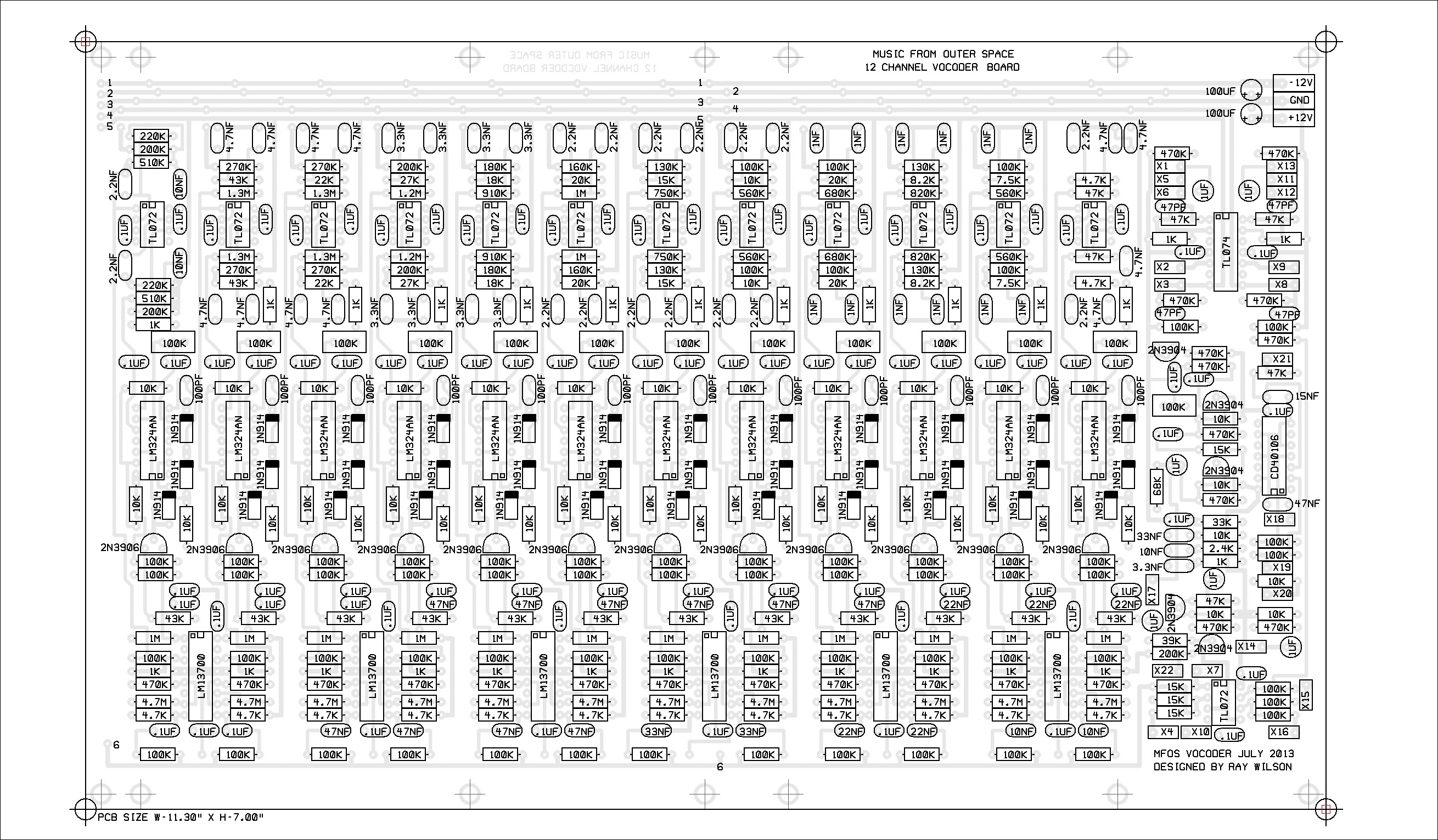
Vocoder PCB Component Values
This view will come in handy during assembly. Just put the correct values where they should go and voila - board populated. Note NF = nF, PF = pF and UF = uF.
Vocoder Expansion
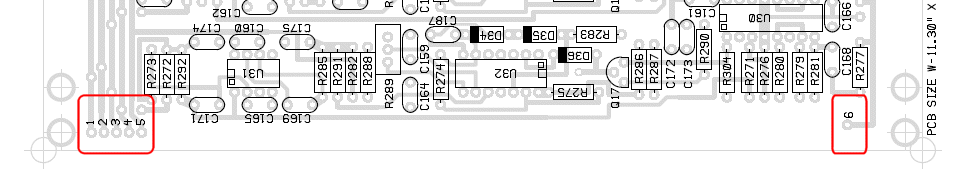
Table of ContentsWhat are those pads with the numbers 1 - 6? They are your ticket to a 22 channel vocoder if you want one. Some people out there are really good at electronics. There might be someone out there that wants to design a new set of filters perhaps making each one's bandwidth narrower and Q a bit higher and going with 22 channels by using two boards. You popluate one board completely but on the second board you will only need to populate the filter sections. Then connect the two boards together (I would mount one on top of the other) by means of the pads labeled 1 through 6. Simply connect pads 1 through 6 between both boards and the slave board will be driven by the main (fully populated board) and the slave board will contribute to the total output of the unit. Even the slave board's highpass and lowpass filter channels can be repurposed to be band pass filters by examining the pads and inserting the components for a band pass filter configuration instead of lowpass or highpass. If you do you may need to mount a resistor or two vertically.
I added the labeled pads at two locations along with additional mounting holes on the PCB because I may come out with a 4-Channel expansion board that would serve the same purpose as using another vocoder board (but with only 4 additional channels) which would be a less expensive option than buying two vocoder PCBs.
- 1 = -12V power
- 2 = +12V power
- 3 = Ground
- 4 = U1 Pin 8 (Audio Filter Driver)
- 5 = U1 Pin 7 (Control Filter Driver)
- 6 = U2 Pin 2 (Inverting input to vocoder output mixer)

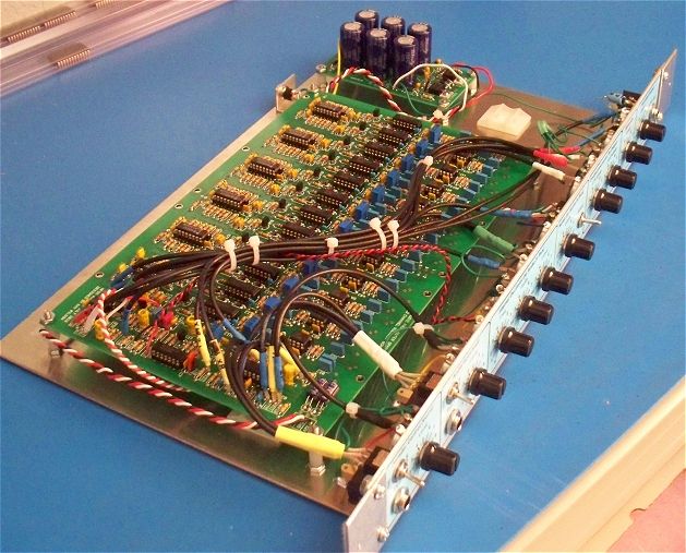
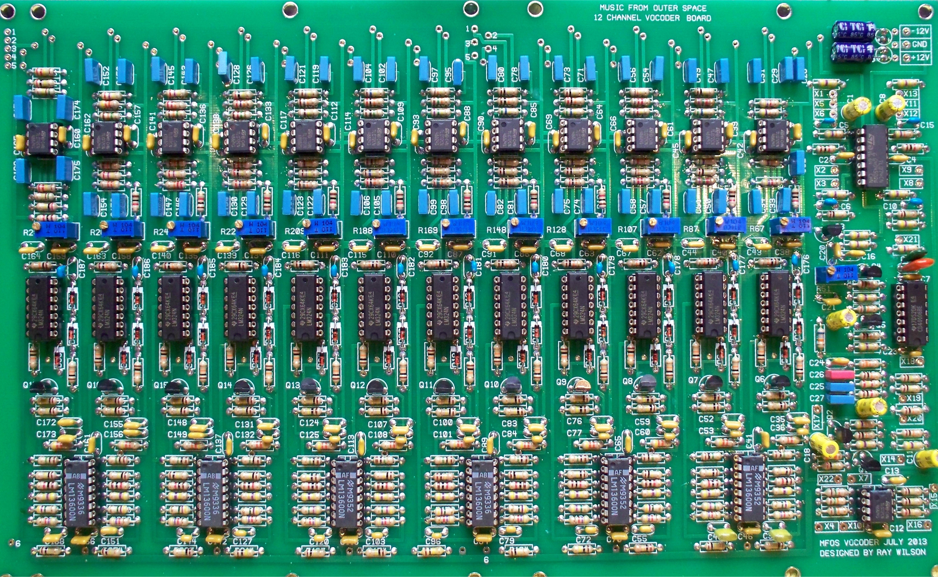
Vocoder PCB Populated
Here is a view of the populated board. Since I did not have a .015uF cap on hand for C19 I had to improvise and use a .01uF in parallel with a .005uF. Not to worry I ordered a bunch of .015uF for the kits so you'll have all the right values. As a matter of fact this is what your project will look like because these are the great majority of parts you will be getting in your kit (including the cool-looking blue metalized film caps).
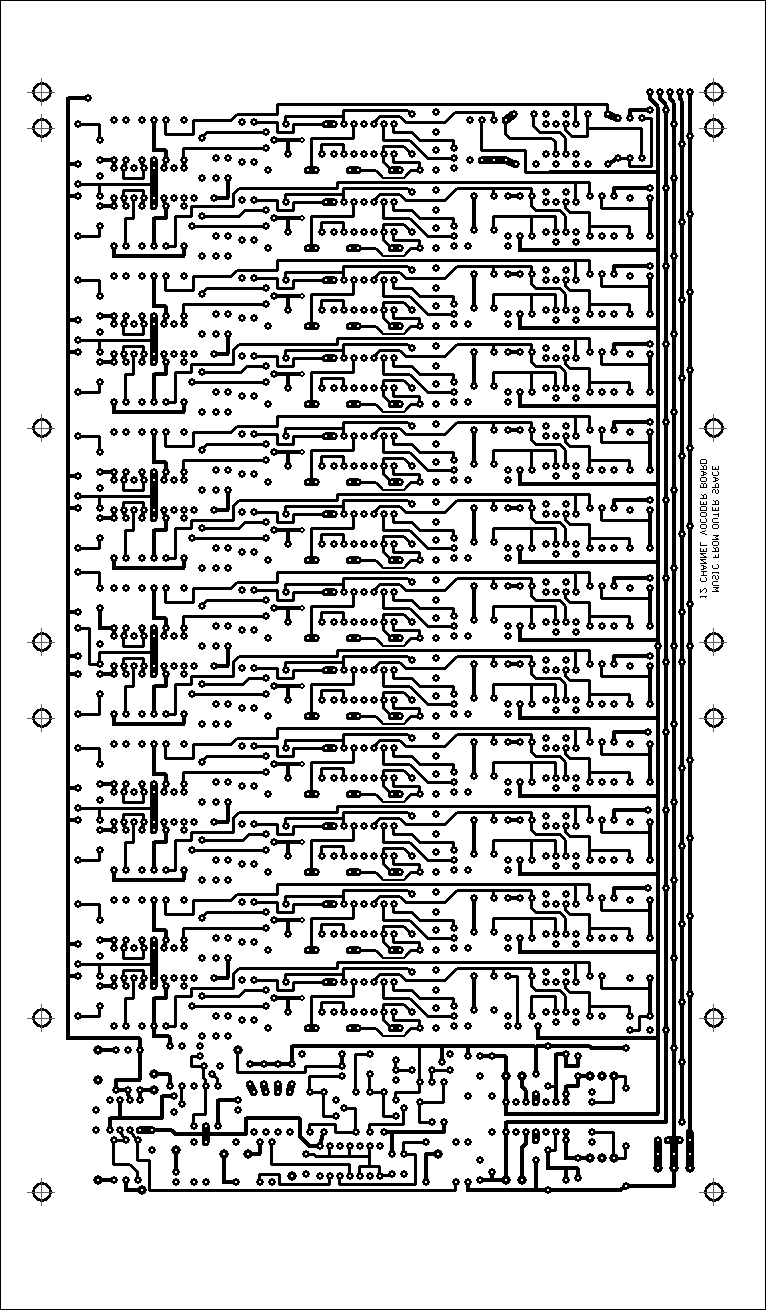
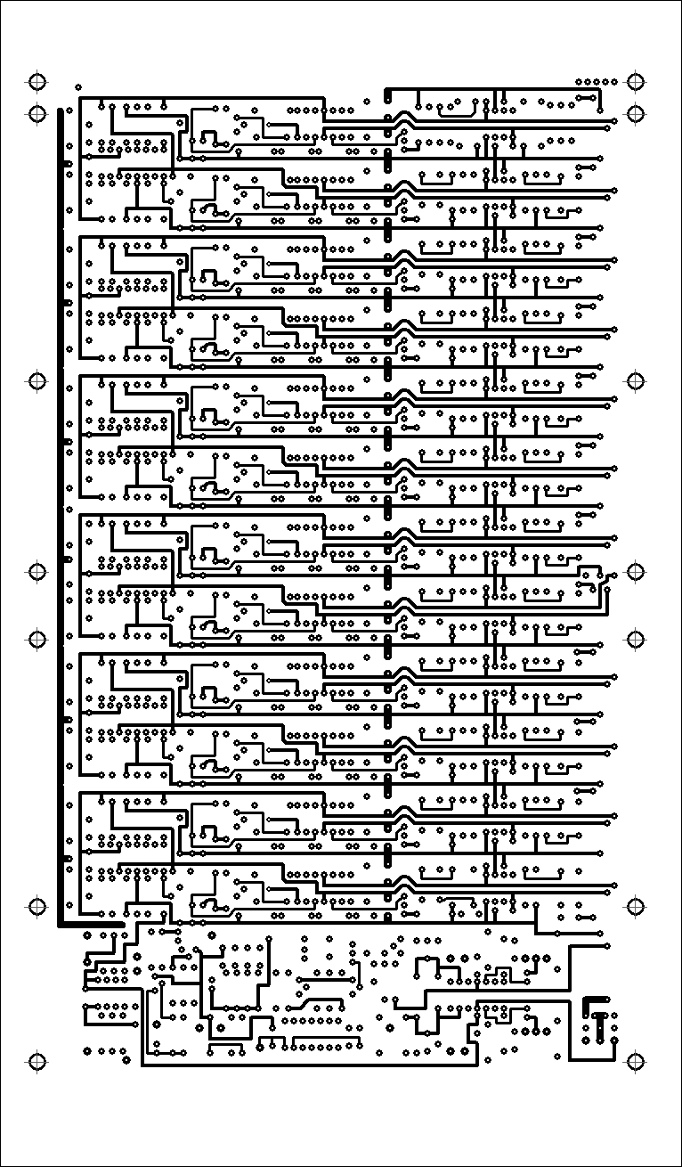
Vocoder PCB Silk Screen

Vocoder PCB Bottom Copper
Note that the image is as seen through the top of the board. For direct PCB process applications you need to 'mirror' the image.
Vocoder PCB Top Copper
Front Panel Information
Table of Contents
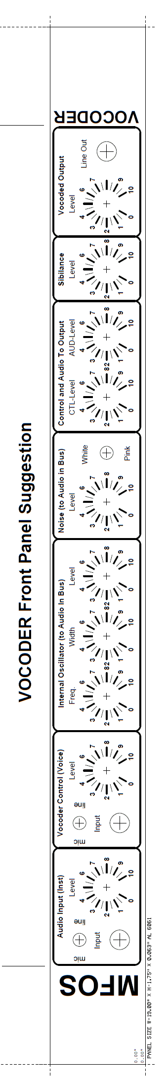
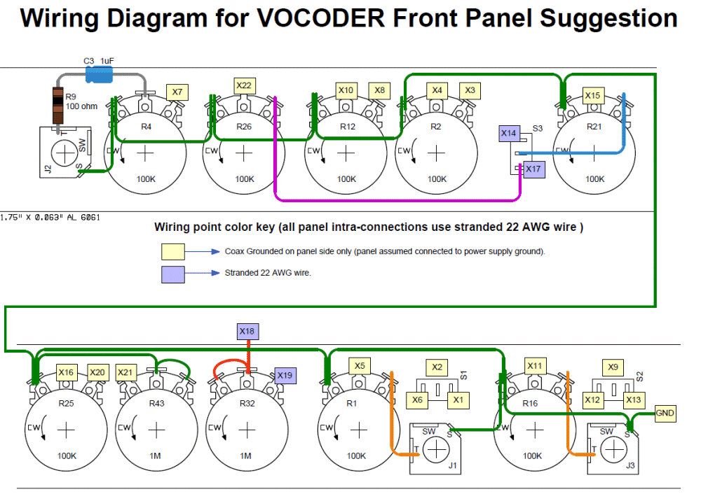
Vocoder Suggested Panel Template and Wiring
View as PDFUse your image processing program to size the panel template to 19 inches wide and it will be to 1 to 1 scale. Alternatively, design a totally cool panel face of your own. Make sure to make an accompanying wiring diagram to avoid wiring issues later.
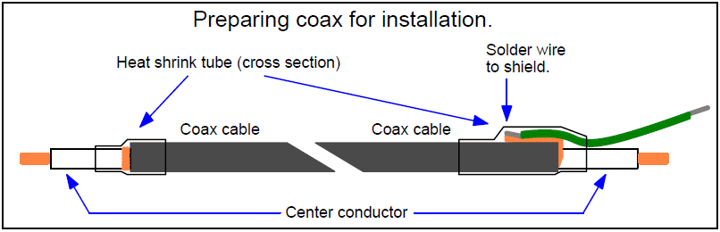
Here is how I prepare coax wire. The heat shrink keeps stray ground wires from getting loose and causing havoc.
Panel Template and Wiring Diagram
The Audio and Control (Voice) inputs and panel controls have been swapped from what I originally published to accomodate wiring the board to the front panel in a more organized way. The orientation of the board in the unit in relation to the panel is shown below these drawings.
I recommend that you find some supple coax cable and use it for most PC board to panel connections. ONLY GROUND ONE END OF THE CABLE. I chose to ground the panel side of the coax since there are so many terminals at ground potential handy. I recommend you do likewise. For the light yellow PC board to panel connection points in the image I ran the same coax wire I plan to send in kits. For the points shown in violet I used stranded 22 AWG wire. Since I ran everything else I thought either made noise or could be influenced by noise in coax to shield it I felt OK using stranded 22 AWG for the remaining connections, which are not - high reflecting signals - in my book.
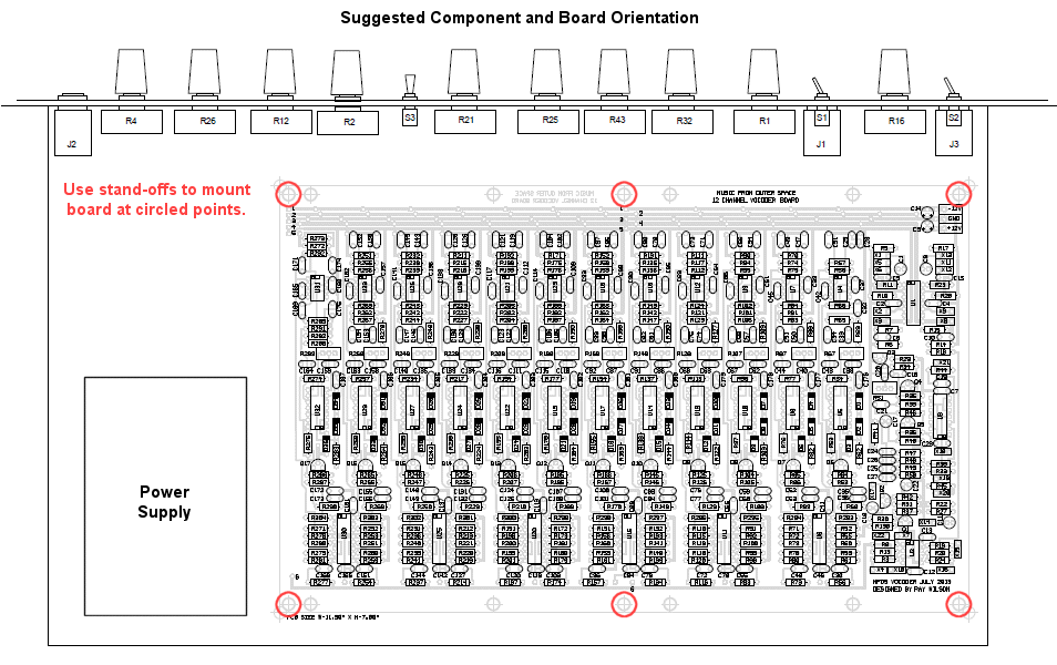
Vocoder Suggested Project Layout
When I built my vocoder I had the Audio and Control (Voice) input positions swapped. When I reoriented my PC board as shown in my unit I found that swapping the panel input locations would make wiring the unit a bit easier. Both the front panel template and the wiring diagram above reflect the Audio/Voice channel input location swap that facilitates wiring to the PC board.
View PC Mounting Hole Dimensions
Parts List (BOM)
Table of Contents
MFOS Vocoder Project Parts List
Parts List PDFAll chips must be DIP (Dual-Inline Plastic or Ceramic) packages. All caps used in the filter sections MUST BE AT LEAST 5% TOLERANCE FILM CAPS or BETTER. Using 5% carbon film resistors will work perfectly and if you want to use 1% resistors they will work perfectly as well. The bypass caps can be ceramic 20% caps but don't scrimp on the filter caps. All of the ceramic and film caps should have lead spacing of 5mm (0.2").
NOTE: C3 (1uF non-polar cap) and R9 (100 ohm resistor) are not located on the circuit board but are installed on the unit's front panel.
| Qty. | Description | Value | Designators |
|---|---|---|---|
| 1 | CD40106 | CD40106 | U3 |
| 6 | LM13700 Dual gm OpAmp | LM13700 | U6, U11, U15, U20, U25, U30 |
| 12 | LM324 Low Power Quad Op Amp | LM324 | U5, U8, U10, U13, U14, U17, U19, U22, U24, U27, U29, U32 |
| 13 | TL072 Dual Op Amp | TL072 | U2, U4, U7, U9, U12, U16, U18, U21, U23, U26, U28, U31, U33 |
| 1 | TL074 Quad Op Amp | TL074 | U1 |
| 5 | Transistor NPN 2N3904 | 2N3904 | Q1, Q2, Q3, Q4, Q5 |
| 12 | Transistor PNP 2N3906 | 2N3906 | Q6, Q7, Q8, Q9, Q10, Q11, Q12, Q13, Q14, Q15, Q16, Q17 |
| 36 | Diode 1N914 | 1N914 | D1, D2, D3, D4, D5, D6, D7, D8, D9, D10, D11, D12, D13, D14, D15, D16, D17, D18, D19, D20, D21, D22, D23, D24, D25, D26, D27, D28, D29, D30, D31, D32, D33, D34, D35, D36 |
| 8 | Linear Taper Potentiometer | 100K | R1, R2, R4, R12, R16, R21, R25, R26 |
| 2 | Linear Taper Potentiometer | 1M | R32, R43 |
| 23 | Resistor 1/4 Watt 5% | 470K | R5, R7, R15, R17, R18, R27, R29, R34, R37, R39, R40, R60, R79, R100, R119, R141, R160, R181, R200, R221, R240, R261, R280 |
| 6 | Resistor 1/4 Watt 5% | 47K | R11, R23, R42, R44, R58, R66 |
| 2 | Resistor 1/4 Watt 5% | 510K | R291, R292 |
| 4 | Resistor 1/4 Watt 5% | 560K | R75, R84, R136, R143 |
| 2 | Resistor 1/4 Watt 5% | 680K | R112, R124 |
| 1 | Resistor 1/4 Watt 5% | 68K | R41 |
| 2 | Resistor 1/4 Watt 5% | 7.5K | R74, R83 |
| 2 | Resistor 1/4 Watt 5% | 750K | R153, R165 |
| 2 | Resistor 1/4 Watt 5% | 8.2K | R94, R106 |
| 2 | Resistor 1/4 Watt 5% | 820K | R95, R102 |
| 2 | Resistor 1/4 Watt 5% | 910K | R193, R205 |
| 2 | Resistor 1/4 Watt 5% | 1.2M | R216, R223 |
| 4 | Resistor 1/4 Watt 5% | 1.3M | R233, R245, R256, R263 |
| 1 | Resistor 1/4 Watt 5% | 100 ohms | R9 |
| 61 | Resistor 1/4 Watt 5% | 100K | R6, R14, R19, R20, R24, R33, R38, R52, R56, R63, R64, R70, R71, R73, R81, R85, R86, R91, R93, R104, R105, R110, R111, R116, R121, R125, R126, R131, R132, R134, R142, R145, R146, R151, R157, R166, R167, R172, R174, R185, R186, R191, R197, R206, R207, R212, R214, R225, R226, R231, R237, R246, R247, R252, R254, R265, R266, R271, R277, R286, R287 |
| 44 | Resistor 1/4 Watt 5% | 10K | R22, R31, R35, R36, R45, R48, R53, R54, R62, R76, R77, R82, R96, R97, R103, R113, R114, R122, R135, R137, R138, R144, R147, R154, R155, R163, R177, R178, R184, R194, R195, R203, R217, R218, R224, R234, R235, R243, R257, R258, R264, R274, R275, R283 |
| 4 | Resistor 1/4 Watt 5% | 130K | R90, R101, R152, R162 |
| 6 | Resistor 1/4 Watt 5% | 15K | R3, R8, R13, R46, R158, R164 |
| 2 | Resistor 1/4 Watt 5% | 160K | R171, R182 |
| 2 | Resistor 1/4 Watt 5% | 180K | R192, R202 |
| 2 | Resistor 1/4 Watt 5% | 18K | R198, R204 |
| 27 | Resistor 1/4 Watt 5% | 1K | R10, R28, R50, R55, R69, R72, R88, R92, R109, R115, R127, R133, R150, R156, R168, R173, R190, R196, R208, R213, R230, R236, R248, R253, R270, R276, R288 |
| 14 | Resistor 1/4 Watt 5% | 1M | R176, R183, R293, R294, R295, R296, R297, R298, R299, R300, R301, R302, R303, R304 |
| 1 | Resistor 1/4 Watt 5% | 2.4K | R49 |
| 5 | Resistor 1/4 Watt 5% | 200K | R130, R211, R222, R272, R282 |
| 4 | Resistor 1/4 Watt 5% | 20K | R117, R123, R175, R187 |
| 2 | Resistor 1/4 Watt 5% | 220K | R273, R285 |
| 2 | Resistor 1/4 Watt 5% | 22K | R238, R244 |
| 4 | Resistor 1/4 Watt 5% | 270K | R232, R242, R251, R262 |
| 2 | Resistor 1/4 Watt 5% | 27K | R215, R227 |
| 1 | Resistor 1/4 Watt 5% | 33K | R47 |
| 1 | Resistor 1/4 Watt 5% | 39K | R30 |
| 14 | Resistor 1/4 Watt 5% | 4.7K | R57, R61, R65, R80, R98, R120, R139, R161, R179, R201, R219, R241, R259, R281 |
| 12 | Resistor 1/4 Watt 5% | 4.7M | R59, R78, R99, R118, R140, R159, R180, R199, R220, R239, R260, R279 |
| 14 | Resistor 1/4 Watt 5% | 43K | R68, R89, R108, R129, R149, R170, R189, R210, R229, R250, R255, R267, R269, R290 |
| 13 | Trim Pot | 100K | R51, R67, R87, R107, R128, R148, R169, R188, R209, R228, R249, R268, R289 |
| 86 | Capacitor Ceramic | .1uF | C2, C4, C7, C12, C13, C16, C20, C21, C24, C35, C37, C38, C39, C40, C41, C42, C43, C44, C45, C46, C52, C59, C61, C62, C63, C64, C65, C66, C67, C68, C69, C70, C76, C83, C85, C86, C87, C88, C89, C90, C91, C92, C93, C94, C100, C107, C109, C110, C111, C112, C113, C114, C115, C116, C117, C118, C124, C131, C133, C134, C135, C136, C137, C138, C139, C140, C141, C142, C148, C149, C151, C155, C156, C157, C158, C159, C160, C161, C162, C163, C164, C165, C166, C168, C172, C173 |
| 12 | Capacitor Ceramic | 100pF | C176, C177, C178, C179, C180, C181, C182, C183, C184, C185, C186, C187 |
| 1 | Capacitor Ceramic | 15nF | C19 |
| 4 | Capacitor Ceramic | 47pF | C5, C6, C10, C15 |
| 5 | Capacitor Ceramic | 22nF | C36, C53, C55, C60, C72 |
| 3 | Capacitor Ceramic | 33nF | C26, C79, C96 |
| 11 | Capacitor Ceramic | 47nF | C23, C77, C84, C101, C103, C108, C120, C125, C127, C132, C144 |
| 7 | Capacitor Alum. Bipolar | 1uF | C1, C3, C8, C11, C17, C18, C22 |
| 2 | Capacitor Electrolytic 16V (small size) | 100uF | C9, C14 |
| 5 | Metalized Polyester Film 5% Capacitor | 10nF | C25, C30, C48, C174, C175 |
| 12 | Metalized Polyester Film 5% Capacitor | 1nF | C47, C49, C50, C51, C54, C56, C57, C58, C71, C73, C74, C75 |
| 16 | Metalized Polyester Film 5% Capacitor | 2.2nF | C31, C34, C78, C80, C81, C82, C95, C97, C98, C99, C102, C104, C105, C106, C169, C171 |
| 12 | Metalized Polyester Film 5% Capacitor | 4.7nF | C28, C29, C32, C33, C143, C145, C146, C147, C150, C152, C153, C154 |
| 9 | Metalized Polyester Film 5% Capacitor | 3.3nF | C27, C119, C121, C122, C123, C126, C128, C129, C130 |
| 3 | Switch SPDT | SPDT | S1, S2, S3 |
| 3 | Jack 1/4" 2 Terminal | 1/4" Phone Jack | J1, J2, J3 |
| 10 | Potentiometer Knobs | Knobs for All Pots |
I'd love to see any pics of completed units. I hope this vocoder helps you make some totally awesome songs, sounds and effects. Best Ray