Ray Wilson authored this content while he was actively running MFOS as the founder and resident genius.
We retain the content because it reflects a valuable point of view representing that time and place.
Article by Ray Wilson
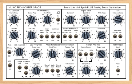
Sound Lab Mini-Synth PLUS with Micro Sample & Hold
This project is a reprise of the Sound Lab Mini-Synth with the addition of a Sample and Hold and several circuit and
component value changes to improve performance. Even if you have already built a Sound Lab I would recommend this as a completely new project.
Of course if you desire to you can mod your existing Sound Lab to match this project. I will call attention to
changes from the original Sound Lab.
|
 |
Introduction
If you have already built a sound lab you can do the mods listed here and improve the functionality of your Sound Lab. Please read the entire page and study the schematics before picking up your solder iron (you'll be glad you did). If you already have a Sound Lab and are happy with it as it is then leave it alone. Why mess with success? I built one anew and it looks almost like the artist's rendering above. Except you get the benefit of not making the mistakes I did and having to do lots of rework. There are kludges that will require some skill but nothing really that difficult. Follow the pictures and drawings carefully and you will have a very cool analog synthesizer to enjoy.This project is kind of like two projects in one and requires 2 circuit boards. A Sound Lab Mini-Synth PCB and the new "MICRO SAMPLE AND HOLD" PCB, both are available for sale under the catalog tab. All of the details for the MICRO SAMPLE AND HOLD are presented in the Micro Sample & Hold tab.
Between the schematics, layout drawings, and photos there are over 50 new images here to help you and 16 new PDFs. On many of the kludge photos if you click you will ge a much larger view. I hope you enjoy the project and I know you'll enjoy the outcome. It has turned the cool factor up to beyond 11 on the Sound Lab Mini-Synth.
Well that's enough introduction. On the project pages accessed by means of the tree or the tabs above you'll find the schematics and everything else you need to build this cool project. If you find glaring errors or omissions please let me know so I can correct them. I'll be getting some sound samples up here soon but I need to eat and take a shower first :-) Enjoy!
Sound Lab Mini-Synth PLUS Block Diagram Kindly Provided By Gene Hammond-Lewis

|
A diyer brought a good point to my attention. The "Micro Sample And Hold" board is marked +/-12V and the Sound Lab is marked +/-9V. His question was "Which should I use?". The answer is... either. Both boards should run off of the same power supply whether it is two 9V batteries wired as +/-9V or a bipolar power supply (in the range of +/-9V to +/-15V). There will be no degradation in the operation of the Micro S&H running off of a +/-9V battery supply. The advantage of using a wall wart powered supply is that with batteries you will get a variation in performance as they discharge whereas the wall wart supply is always the same. So there you have it and sorry for any confusion this caused. That's me uttering "DOH!" by the way. :-) |