Article by Ray Wilson
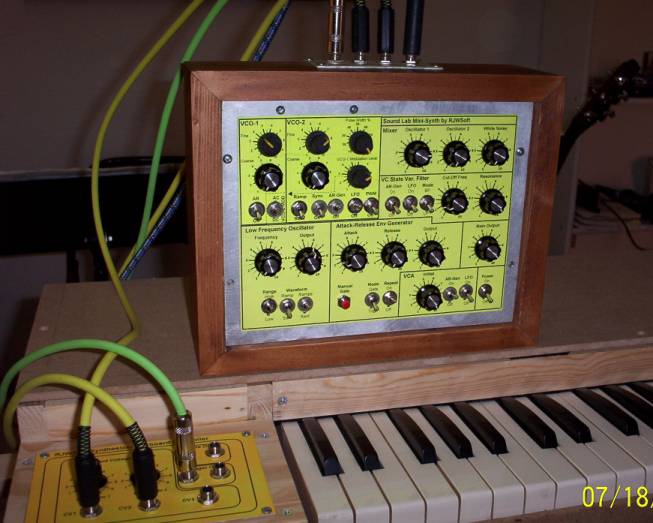
My Modified Sound LabI added the VCO scaling, Osc 1 modulated by Osc 2, and the fine tuners modifications.
I removed the original controls and then carefully drilled some new holes. I then pasted the portion of the panel that changed onto the original. I had to use small body pots for all six of the pots involved with the oscillator mods. Normal ones might have fit but it would have been very tight.
|
Protect The External CV Inputs From Higher Voltage [Top]If you are afraid of applying too much voltage to the external CV inputs then protect them with zener diodes as shown. If the CV voltage exceeds the zener voltage the zener diode will conduct and limit the input voltage to 9.1 volts. The CV Summer OpAmp inputs are IC5-B pin 6 for oscillator 1 and IC6-B pin 6 for oscillator 2. |
 |
Adding More CV Inputs to The Sound Lab Oscillators [Top]
|
Adding LED Indicators [Top]If you want to add LED indicators here is how. Bear in mind that the LEDs will eat current and kill your batteries faster though. Since the LFO indicator is driven by the ramp/tri wave it will fade in and out at the LFO frequency.
|
Patching Out The Sound Lab [Top]If you're wondering how to make a patched out version of the Sound Lab Mini-Synth instead of the normallized version here are some guidelines. I will be adding to this page as I have opportunity and ideas. Obviously this is just my first shot at this. I think if you have some electronics savvy you will be able to do whatever you want after reviewing these guidelines. You can use banana jacks or you can use phone jacks. Just ground the ground lead of the jacks to the ground of the unit and you will be fine. |
PrintingWhen printing these pages You need to set your page orientation to landscape and set the margins as low as they will go. If necessary use cut and paste to put the larger images into your word processor or image editor and then print them from there. I have not been able to figure out why Internet Explorer adds several blank pages (does Bill have stock in some paper companies?). |
Sound Lab Mini-Synth AR (Attack - Release) Envelope Generator
Sound Lab Mini-Synth LFO (Low Frequency Oscillator),
Noise Source, and +/- 9 Volt Battery Power Supply
Sound Lab Mini-Synth VCA (Voltage Controlled Amplifier) and
VCF (Voltage Controlled Filter)
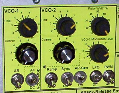
Sound Lab Mini-Synth VCOs (Voltage Controlled Oscillators)
Modulate Oscillator 1 With Oscillator 2 [Top]To get some cool modulation effects you can modulate VCO-1 with the output of VCO-2.This first circuit assumes the patched out version. You need to add a new 100K pot, two switches (SPDT and SPST) and the 100K resistor and 2uF capacitor. This configuration allows you to choose the mod source independent of the wave setting of Osc 2. "Osc 2 Out" is IC6-D pin 14 and "Osc 2 Out Pulse" is the junction of R80 pin 2 and R81 pin 1. (You could also use IC2-A pin 1 for a non-attenuated version of the "Osc 2 Out Pulse" signal).
This circuit assumes the non-patched out version. You need to add a new 100K pot and one switch (SPST) to the front panel and the 100K resistor and 2uF capacitor. I recommend you solder the resistor and cap to the switch and pot terminals and then run wires to the PC board as needed. This configuration causes the mod source to be controlled by the wave setting of Osc 2.
|
Sound Lab Mini-Synth VCO Fine Tuners [Top]Add these extra pots in order to allow fine tuning of the oscillators. |