Ray Wilson authored this content while he was actively running MFOS as the founder and resident genius.
We retain the content because it reflects a valuable point of view representing that time and place.
Article by Ray Wilson
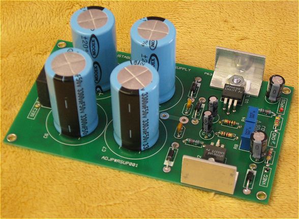
This is a great bipolar power supply for your modular synthesizer project. This LM317/LM337 based supply boasts 1.5A capability and adjustable output so you can supply your projects with anything between +/-9 and +/-15 volts.
As you can see below, you will need to heat sink the regulators if you plan to draw the maximum power this supply can deliver. I would even suggest larger heat sinks than those shown. I made these from aluminum 'L' channel and if they start to get too warm as I add modules I will increase the size of them to dissipate more heat.
Also, single turn trimmers will work but multi-turn will allow you to set the voltage with more accuracy.
I list 10,000 uF caps in the parts list for the main supply smoothing caps and these will give you excellent supply smoothing but if you find caps that fit .4" spacing that are larger or smaller in capacity (3300 uF to 15,000 uF) they will still work for lower currents so don't get too hung up trying to find 10,000 uF electrolytics. I also list tantalum for some caps for best results but aluminum electros will again work as well. The more current you plan to draw from the supply the larger you should make the main smoothing caps.
Adjustable LM317/LM337 1.5A Supply Schematic
Not a whole lot to describe really. This board is based directly on the best practice circuit for these chips described in the National Semiconductor's data sheets for the LM317 and LM337. The 2K trimmers are used to adjust the output voltages independently. Adjust the output to the desired voltage while monitoring each with a good DVM and you are ready to go.
Adjustable LM317/LM337 1.5A Supply Part Designators
Adjustable LM317/LM337 1.5A Supply Part Values
Adjustable LM317/LM337 1.5A Supply PCB Bottom Coppper
Adjustable LM317/LM337 1.5A Supply PCB Top Coppper
Adjustable LM317/LM337 1.5A Supply PCB Silk Screen
Adjustable LM317/LM337 1.5A Supply Project Parts List
| Qty. | Description | Value | Designators |
|---|---|---|---|
| 1 | Bridge Rectifier | KBU401 (or equivalent) | BR1 |
| 1 | LM317T Adj. Pos. Voltage Regulator | LM317T | U1 |
| 1 | LM337T Adj. Neg. Voltage Regulator | LM337T | U2 |
| 2 | Resistor 1/4 Watt 1% | 1K | R3, R7 |
| 2 | Resistor 1/4 Watt 1% | 240 ohm | R1, R5 |
| 2 | Resistor 1/4 Watt 1% | 4.7K | R2, R6 |
| 2 | Trim Pot (multi-turn preferrable) | 2K | R4, R8 |
| 4 | 1N4002 | 1N4002 | CR2, CR1, CR3, CR4 |
| 2 | Capacitor Ceramic | .1uF at least 35V | C2, C8 |
| 4 |
Electrolytic Capacitor (35V or 25V) 0.4" (10mm) lead spacing
Caps of this style fit the board. Enter the part# in the search at Mouser.com Mouser part# 598-SLPX153M025C7P3 (15,000uF 25V)Mouser part# 598-SLPX103M035E3P3 (10,000uF 35V) Mouser part# 598-SLP153M025C4P3 (15,000uF 25V) Mouser part# 598-SLP103M035C7P3 (10,000uF 35V)
|
10000 to 15000uF 25V or 35V | C4, C5, C6, C7 |
| 2 | Tantalum Electrolytic Capacitor | 10uF 35V | C3, C10 |
| 2 | Tantalum Electrolytic Capacitor | 1uF 35V | C1, C9 |