Ray Wilson authored this content while he was actively running MFOS as the founder and resident genius.
We retain the content because it reflects a valuable point of view representing that time and place.
Article by Ray Wilson
This is an intermediate to advanced project and I do not recommend it as a first project if you are just getting started in synths or electronics. Only the circuit and some explanation are shown here. A lot of project building, troubleshooting and electronics experience is assumed. Additionally, electronic equipment ownership (scope, meters, etc.) is taken for granted. If you are interested in building this project please read the entire page before ordering PC boards to ensure that the information provided is thorough enough for you to complete the project successfully.
Introduction
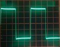
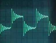
This is a really good filter. Some people have told me that it compares with the Moog filter (warning! that may just be kooky talk). It features adjustable resonance. With the resonance setting at minimum (no resonance) as you sweep the filter's cut-off frequency your input signal goes from nothing (if its fundamental frequency is below the cut-off frequency) to your original waveform with all its sharp little corners and timbres. As you advance the resonance control and sweep the filter your waveform's sharp corners (fast voltage changes) will induce the filter to ring and you will get the sweeping resonances of a Hoomi singer. Hoomi singers use oral formant filtering to produce a unique harmonic filled droning vocal music.
| Resonance at minimum | Resonance turned up |
 |
 |
If you advance the resonance control all the way up the filter will act as a really nice sine wave oscillator.
Adjustment
To set the V/Oct trim apply ground to one of the control voltage inputs and then advance the resonance all the way up and adjust the panel mounted "Init Freq" control so that the filter
oscillates at 1KHz. Apply 1V to the control voltage input (the one you had previously grounded) and adjust the V/Oct trim so that you get 2KHz. Apply 2V to the control voltage input and adjust the
V/Oct trim so that you get 4KHz. I did not count on this filter being exactly 1V/Oct but it will be close so adjust it for the range you are interested in.
As you can see the filter consists of four filter sections and the exponential control current generation section. The LM13700s (in conjunction with the TL084s in their feedback loops) act as current controlled integrators. The resonance control is actually feeding the output of the filter back to its input with heavy emphasis on the cut-off frequency. When the fed-back signal is all the way up the filter sustains oscillation.
VCF Schematic
VCF PC Board Layout (Component Side View)
VCF Board Parts Placement Diagram