Ray Wilson authored this content while he was actively running MFOS as the founder and resident genius.
We retain the content because it reflects a valuable point of view representing that time and place.
Article by Ray Wilson
This is an intermediate to advanced project and I do not recommend it as a first project if you are just getting started in synths or electronics. Only the circuit and some explanation are shown here. A lot of project building, troubleshooting and electronics experience is assumed. Additionally, electronic equipment ownership (scope, meters, etc.) is taken for granted. If you are interested in building this project please read the entire page before ordering PC boards to ensure that the information provided is thorough enough for you to complete the project successfully.
Introduction
The function of this dual VCA is very similar to the other one. It uses one less chip but one more transistor. It uses the built in LM13700 buffers instead of OP-AMPs. You can never have enough VCAs so build build build... I built the circuit board and it works perfectly. I am using about + and - 4 to 5 volts signal in. You can use a higher level of signal in BUT you need to increase R17 (and R37) proportionally. That is, if you want to use + and - 8 to 10 V signals then double the value of R17 (and R37), etc.
The CV Offset adjust pot should be panel mounted. Its purpose is to offset whatever control voltage you are using to control the VCA. I have noticed that for control signals that are operating about ground (i.e. + and - 4 to 5 volts) the pot is usually toward the left when set to linear response and usually toward the right when set to exponential response. I changed the CV offset adjust pot to be connected to -12V instead of ground because I found I needed that much offset adjustment when driving the CV with 0 to 10 volt control voltage sources.
You can overdrive this so watch your signal level and the setting of CV Offset adjust R1 (and R21). Of course overdriving it produces some interesting timbres... so experiment. I built 2 of these boards (resulting in four VCAs) into one module and it rocks.
Dual Voltage Controlled Amplifier #2 Schematic (pg. 1)

Dual Voltage Controlled Amplifier #2 Schematic (pg. 2)
Dual Voltage Controlled Amplifier #2 PC Layout (Parts Side View)
Dual Voltage Controlled Amplifier #2 Parts Placement
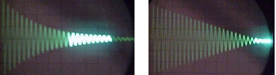
Dual Voltage Controlled Amplifier #2 Response
to a Sawtooth wave control voltage
This highlights the difference between the log (on the left) and linear (on the right) response to the control voltage. The scope was at 2V/div.
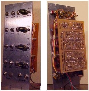
Ugly Photo of Dual Voltage Controlled Amplifier #2
(I do plan to letter the panel... eventually)
I built two of these onto one circuit board (along with the pink/white noise generator to take up the extra space)
Parts BOM (Kindly provided by DIYer Joe Beuckman)