Ray Wilson authored this content while he was actively running MFOS as the founder and resident genius.
We retain the content because it reflects a valuable point of view representing that time and place.
Article by Ray Wilson
Go to Micro Sample n' Hold June 2011 (NEW VERSION)
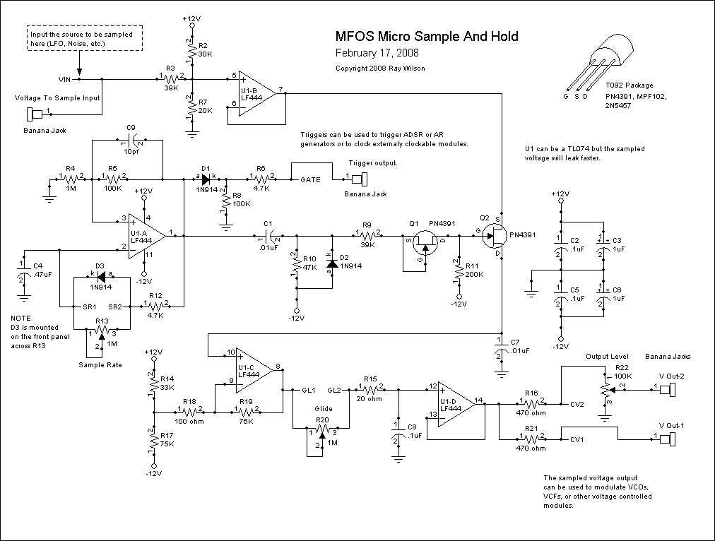
The MFOS Micro-Sample & Hold is a nice addition to your voltage controlled sound generator project whether it's a Synth-DIY Experimenter PC Board project, Sound Lab Mini-Synth or large modular synth project. It is as simple as a Sample & Hold can be yet features variable sample rate and output voltage glide (portamento). Its a simple way to add more flexibility to your synthesizer.
Voltage at the output of U1-B is presented to the source input of Q2 (PN4391).
U1-A and associated components (R4, R5, C9, C4 R13, D3 and R12) comprise a single op-amp pulse generator. The rate at which the pulses occur is determined by the setting of R13 and the size of C4. The values shown give a good range of from approximately .5 HZ to about 50 hz. The leading edge of each pulse is fed via C1 and R9 and Q1 to the gate of Q2. The pulses turn on Q2 causing a sample of the voltage at pin 7 U1-B to charge C7 (polystyrene or other low leakage cap). When Q2 turns off C7 holds the voltage and presents it to U1-C high impedance buffer. I found that the LF444 was the lowest leakage (highest impedance) op-amp and resulted in minimum droop. My experiments with TL074 showed a lot more droop so it's worth finding and buying the LF444.
U1-C biases the sampled voltage so that it is back to the levels it had prior to being biased by U1-B. The voltage at U1-C's output pin 8 is presented to C8 via 1M Glide pot R20, and R15 20 ohm resistor. U1-D buffers the voltage on C8. When R20 1M pot in series with R15 20 ohm resistor presents resistance between pin 8 and pin 12 of U1-D the voltages slide from sample to sample. The more the resistance the slower the glide between samples. The lower the resistance the faster the glide with the glide being imperceptible at minimum resistance.
The output of U1-D feeds the Output Level pot R22 via R16 from point CV1. Point CV2 can also be used as a source for the sampled voltage output.
The sampling pulse is about 4 mS wide and is also used as the trigger output via D1 and R6 (marked as GATE). It started out as a gate (I didn't originally have the diode across R13) but when the output of the oscillator was square I could hear a perceptible drop in the output voltage when the square wave went low. I tried EVERYTHING to get rid of it to no avail. My solution was to make the pulse narrow enough so that if there is still a drop as the pulse goes low it happens so quickly after the sample that I can't hear it so good enough is good enough.
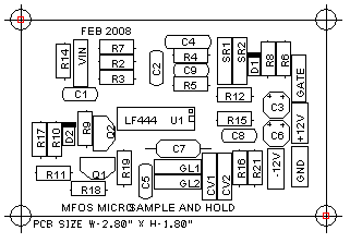
| Micro Sample & Hold Board Details |
|
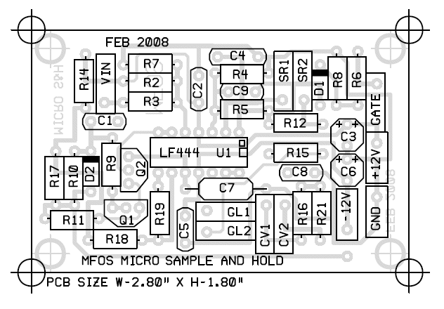
Micro Sample & Hold PC Board Parts Legend
|
|
 |
|
|
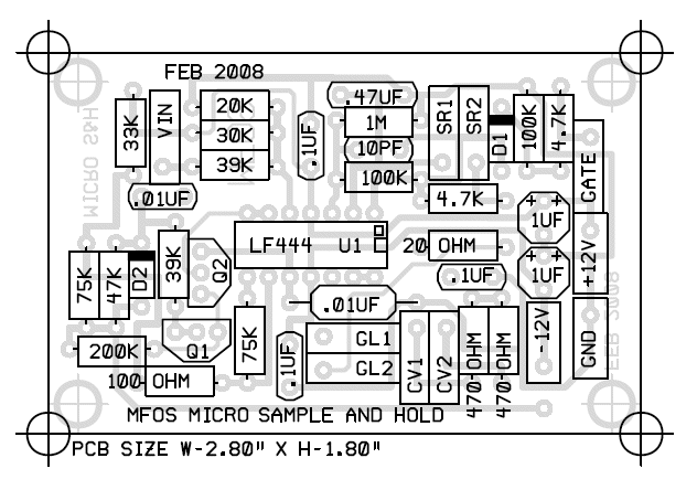
Micro Sample & Hold PC Board Parts Values
|
|
 |
|
|
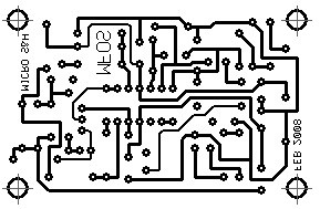
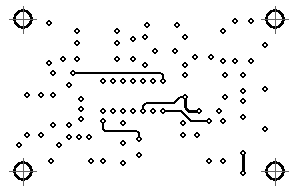
Micro Sample & Hold PCB Layouts
|
|
 |
|
 |
|
 |
|
|
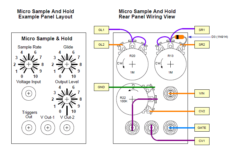
Micro Sample & Hold Panel Example And Wiring Diagram
Here are the essential details to wiring the Micro Sample & Hold to a panel for stand-alone operation. It makes a great modulation source for the Synth-DIY Experimenter Board, the Sound Lab Mini-Synth or your modular synth. |
|
|
|
|
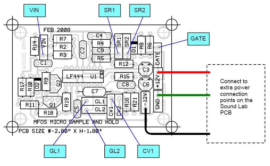
Micro Sample & Sound Lab Plus Wiring Diagram
Here are the essential details to wiring the Micro Sample & Hold to the Sound Lab Plus |
|
|
Micro Sample & Hold Project Parts List
| Qty. | Description | Value | Designators |
|---|---|---|---|
| 1 | LF444 Quad Op Amp | LF444 14P DIP | U1 |
| 2 | PN4391 | PN4391 T092 (or equiv.) | Q1, Q2 |
| 3 | 1N914 Sw. Diode | 1N914 (or equiv.) | D2, D1, D3 |
| 1 | Ceramic Capacitor | .01uF | C1 |
| 1 | Ceramic Capacitor | .47uF | C4 |
| 1 | Ceramic Capacitor | 10pf | C9 |
| 3 | Ceramic Capacitor | .1uF | C2, C5, C8 |
| 2 | Electrolytic Capacitor | 1uF | C3, C6 |
| 1 | Polystyrene (or other low leakage type) Capacitor | .01uF | C7 |
| 1 | Linear Taper Pot | 100K | R22 |
| 1 | Linear Taper Pot | 1M | R13 |
| 1 | Audio Taper Pot | 1M | R20 |
| 1 | Resistor 1/4 Watt 5% | 100 ohm | R18 |
| 2 | Resistor 1/4 Watt 5% | 100K | R8, R5 |
| 1 | Resistor 1/4 Watt 5% | 1M | R4 |
| 1 | Resistor 1/4 Watt 5% | 20 ohm | R15 |
| 1 | Resistor 1/4 Watt 5% | 200K | R11 |
| 1 | Resistor 1/4 Watt 5% | 20K | R7 |
| 1 | Resistor 1/4 Watt 5% | 30K | R2 |
| 1 | Resistor 1/4 Watt 5% | 33K | R14 |
| 2 | Resistor 1/4 Watt 5% | 39K | R3, R9 |
| 2 | Resistor 1/4 Watt 5% | 4.7K | R12, R6 |
| 2 | Resistor 1/4 Watt 5% | 470 ohm | R16, R21 |
| 1 | Resistor 1/4 Watt 5% | 47K | R10 |
| 2 | Resistor 1/4 Watt 5% | 75K | R17, R19 |
| 4 | Banana Jacks | ||
| 3 | Pot Knobs |