Ray Wilson authored this content while he was actively running MFOS as the founder and resident genius.
We retain the content because it reflects a valuable point of view representing that time and place.
Article by Ray Wilson
I have made some significant changes (I believe they are improvements) to the mixer design on the SUB-COMMANDER. They are shown in the schematics, drawings and parts list below. I also suggest changing the value of some of the caps to 2.2uF non-polarized aluminum in order to preserve the low end of the sub-octave and pulse signals throughout the signal chain. Only part replacement, removal and some panel wiring changes are needed. No trace cutting is necessary.
I would like you to understand that this circuit will not take the signal from your guitar, analyze it's frequency, generate a proportional control voltage and then control a multiple waveform oscillator so that you can make your guitar sound like a Moog synthesizer. What it does is buffer your guitar's signal, create a pulse waveform (at the same frequency as the guitar) divide it's frequency in half (sub-octave generator) and generate a gate when you pluck a string so you can control the SUB-COMMANDER's AR generators. It permits you to mix the sub-octave, original signal and pulse signal and then route them through the SUB-COMMANDER's VCF and VCA. By doing this you can generate some very cool synthesizer-like sounds and effects for your electric guitar. (Some sound samples are available below.)
This is not to be compared with units that require a hex pickup and special processing to drive frequency to voltage convertors or MIDI controllers.
Features
User Feedback
Sound Samples (raw with no effects)Auto-Wah Auto-Wah And Sub-Octave Fade In VCA Fade Out VCA Original And Sub-Octave Percussive Pulse And Drum Track Ring Moddish Synthy Stuff Tremolo Tuba Anyone WoW WoW WoW WoW Plus Original Keyboards can be augmented.
|
|
Introduction
The SUB-COMMANDER is a great project for the advanced electronics hobbyist/guitar player. I think there are quite a few of us out there. Obviously you can buy this functionality in a "Digi-Tech" stomp box with no soldering, troubleshooting, or swearing involved but heck... what fun is that? By the time you complete this project you will have built:- A guitar sub-octave generator
- A guitar to gate & trigger generator
- An audio mixer.
- Two AD/AR generators.
- Two Triangle wave LFOs.
- A 12dB/octave lowpass VCF (Voltage Controlled Filter)
- A exponential response VCA (Voltage Controlled Amplifier)
SUB-COMMANDER Guitar Synthesizer Page 1 PDF
Old REV0 Schematic Old REV0 Schematic PDF
- The pad formerly used for R16 that connects to U3 pin 13 becomes point X2 and is wired to the non-grounded side of panel mounted pot R42.
- The pad formerly used for R22 that connects to U3 pin 11 becomes point X1 and is wired to the non-grounded side of panel mounted pot R41.
- The pad formerly used for R38 that connects to U1 pin 7 becomes point X3 and is wired to the non-grounded side of both panel mounted pot R43 and panel mounted pot R45.
|
Page one of the schematic contains the input preamplifier, 3 pole fixed low pass filter, peak/valley detectors,
and pulse generator. Additionally the sub-octave divider and signal to gate generator are shown.
U1-A and U1-B along with their associated resistors and capacitors comprise the input signal buffer. The instrument signal is applied to U1-A's non-inverting input via C1 and R1. R7 and R12 cause U1-A to have a gain of 2. R6 holds the high impedance non-inverting input of U1-A at ground potential. Guitar pickups vary in their output. If you need/want more initial gain from your guitar you can add gain by lowering the value of R12 to as low as 7.5K. The gain is determined by (the value of R7 divided by the value of R12) + 1. This idea was contributed by builder Charles DeCraene of California, USA. U1-A's output is applied via C2 to the non-inverting input of U1-B (also held to ground via R8 1M resistor). R9 and R13 cause U1-B to have a gain of about 4.8. The combination of U1-A nd U1-B provide a gain of about 9.7 to the input signal. Even with a hot guitar signal the level at U1-B pin 7 (point "CG" (Clean Guitar)) is well within the non-distorting level of output voltage for the TL074. If you see distortion at all at point "CG" (clean guitar) then turn your guitar's knobs down a bit. U1-C, U1-D and associated components comprise a 3 pole low pass (Sallen Key) filter. This filter's purpose is to reduce the high frequency harmonics contained in the original guitar (or instrument) signal and accentuate the fundemental frequency. This allows the following circuitry to more accurately track the fundamental during pulse generation and subsequent division by two. The output of the filter is capacitively coupled via C6 and dropped on R11 (1M resistor to ground). The signal across R11 is applied to the non-inverting inputs of U2-B, U2-C, and U2-D and the inverting input of U2-A. The diode in the feedback loop of U2-C charges C7 via R17 during the positive half of the guitar signal cycles. D2 prevents the output of U2-C from discharging C7 during the low half of the guitar signal cycles. During the low half of the cycle U2-C acts like a comparator and goes as close to the negative supply level as it can. This is because diode D2 blocks the output signal from reaching the non-inverting input and U2-C pin 8 goes nuts trying to cause the voltage at the inverting input to equal the voltage at the non-inverting input. R15 and R18 bias the inverting input of U2-D up to about 120 mV. R18 tends to discharge C7 to that level with a time constant of about 1/100 of a second. Thus C7 is repeatedly charged to a diode drop below the guitar cycle peaks by U2-C so it tends to maintain that value when the guitar (or instrument) signal is present. When no signal is present C7 goes to about 120 mV (the voltage at the junction of R15 and R18). The reason for holding the non-inverting input slighlty above ground is so the signal from simply holding the guitar or touching the strings doesn't cause the output of U2-D (the positive half cycle comparator) to go high. During positive half cycles the voltage at the non-inverting input of U2-D is higher than the voltage on it's non-inverting input but note that it goes low again faster than the voltage on C7 which has to discharge via R18 so U2-D's output shoots high during the signal peak but then goes low again as soon as the voltage at U2-D pin 12 goes lower than the voltage on U2-D pin 13. The pulse appearing on U2-D's output (pin 14) is fed via forward biased diode D1 and dropped on R19 where it causes U3-A (1/2 of the CD4013 Dual D Flip Flop) to be set. When the set pin is pulsed U3-A's pin 1 goes and stays high until U3-A is reset by a pulse applied to it's reset input. That pulse comes from U2-A pin 1 via diode D3 where it is dropped across R21. Note that U2-B is permitting the low halves of the input signal to discharge C8 to the negative peak voltage of the signal. C8's voltage is presented to the non-inverting input of U2-A (pin 3). When the signal voltage (applied to the inverting input of U2-A pin 2) goes lower than the voltage on U2-A pin 3, U2-A's output goes high until the signal voltage on U2-A pin 3 returns to a level higher than the voltage on U2-A pin 2. At that time the output of U2-A goes low again. The timing diagram below illustrates the pulse generation and the sub-octave generation occurring as the input signal oscillates. |
SUB-COMMANDER Pulse and Sub-Octave Generation Timing Diagram PDF
|
At the positive peak of the input signal C7 is charged to slightly less than the original signal voltage being
presented to the non-inverting input of U2-D, pin 12. Since C7's voltage is presented to the inverting input of U2-D
(being used as a comparator) U2-D's output goes from about -10.5 volts to about +10.5 volts and sets U3-A (1/2 of Dual D-Flip
Flop CD4013) via diode D1. D1 blocks the negative voltage at U2-D's output from reaching U3-A pin 6 since negative voltage
applied to the single supply CMOS chip will damage it. U3-A's pin 6 sees ground via R19 (when U2-D's output is at -10.5 volts)
or +10.5 volts (when U2-D's output is high). When the input signal starts to go low it eventually goes below the voltage that
is still seen on C7 since C7 discharges relatively slowly via R18 (100K). At that point the output of U2-D returns low
(about -10.5 volts).
At the negative peak of the input signal C8 is dis-charged to slightly more than the original signal voltage being presented to the inverting input of U2-A, pin 2. Since C8's voltage is presented to the non-inverting input of U2-A (being used as a comparator) U2-A's output goes from about -10.5 volts to about +10.5 volts and resets U3-A (1/2 of Dual D-Flip Flop CD4013) via diode D3. D3 blocks the negative voltage at U2-A's output from reaching U3-A pin 4. U3-A's pin 4 sees ground via R21 (when U2-A's output is at -10.5 volts) or +10.5 volts (when U2-A's output is high). When the input signal starts to go high it eventually goes above the voltage that is still seen on C8 since C8 recharges relatively slowly via R25 (100K). At that point the output of U2-A returns low (about -10.5 volts). Thus U3-A is set and reset on each input signal cycle resulting in a rectangular wave that has the same frequency as the input signal at pin 1 of U3-A. That signal is used to clock the D-Flip Flop U3-B which is set up to divide the input clock by 2. Every time a clock edge is applied to U3-B pin 11 the logic level applied to the data input (in this case the logic level seen at the /Q (not-Q) output is propogated to the Q output (and then the /Q output assumes the opposite logic level). Thus the D-Flip Flop clocks in a 1 then clocks in a 0 then a 1 then a 0, etc. This results in two clock cycles being required for every one cycle of low to high (or high to low) at the Q output of U3-A. Thus, Hence and so… the Q output of U3-A becomes the sub-octave signal. |
SUB-COMMANDER Gate Generation Timing Diagram PDF
| The signal applied to the non-inverting input of U4-A (pin 3) is rectified by the diode in the feedback loop of U4-A. U4-A also provides a bit of gain to the input signal that it is rectifying (via R33 and R32). The positive excursions of the input signal are presented to the inverting input of U4-B (pin 6). U4-B is used as a comparator and voltage divider R27 and R28 apply 1/3 of the positive supply voltage to it's the non-inverting input (pin 5). When the output of U4-A (pin 1) goes above the threshold set by R27 and R28 the output of U4-B (pin 7) goes to about -10.5 volts. When the output of U4-A (pin 1) goes below the threshold set by R27 and R28 the output of U4-B (pin 7) goes to about 10.5 volts. The positive excursions of U4-B's output (pin 7) cause pin 2 of U5 and the base of PNP transistor Q1 to be held at about +10 volts. When U4-B's output goes low D6 blocks the negative excursion from being seen on U5 pin 2 and and the base of PNP transistor Q1 but allows both of them to see ground through R35 20K resistor. The high to low transition does two things it triggers the LMC555 timer to begin timing out (U5 pin 3 goes high) and it turns on Q1 so that Q1 discharges U5's timing cap C17. Having the PNP Q1 in the circuit is called using the 555 in retriggered mode. This causes U5 to stay high as long as an input signal with amplitude sufficient to keep toggling U4-B's output is present. Once the input signal subsides (U4-B is no longer toggled) the 555 times out the last cycle and returns low. |
SUB-COMMANDER Guitar Synthesizer Page 2 PDF
Old REV0 Schematic Old REV0 Schematic PDF
- The pad formerly used for R38 that connects to U1 pin 7 becomes point X3 and is wired to the non-grounded side of both panel mounted pot R43 and panel mounted pot R45.
- Remove the .1 uF ceramic capacitors: C20, C21, and C25 and replace them with 2.2uF non-polarized aluminum caps.
- Remove 30K resistor R39 and replace it with a 300K resistor.
- The pad formerly used for R16 that connects to U3 pin 13 becomes point X2 and is wired to the non-grounded side of panel mounted pot R42.
- The pad formerly used for R22 that connects to U3 pin 11 becomes point X1 and is wired to the non-grounded side of panel mounted pot R41.
This is the mixer section of the SUB-COMMANDER. The PLS (pulse) output from page 1 and SUB (sub-octave) output from page 1
are applied to the non-grounded side of volume pots R41 and R42 respectively. You can use linear or log pots for these.
Log pots are designed to raise the volume logarithmically which is causes our ears to notice the change in volume more readily.
Using linear pots will work just as well. The wipers of R41 and R42 connect to the PC board's MX1 and MX2 connection points
respectively. These points both connect through 2.2uF non-polarized aluminum caps into 300K resistors which are connected to the
non-inverting input (summing node) of U6-A. The "CG" (clean guitar) signal is applied to the non-grounded side of R43 and the
non-grounded side of R45. R43 is pot which sets the level of the clean signal on it's way to the VCF and VCA. R45 sets the level
of the clean signal that is fed to the main output buffer U6-B via C23 .1uF and R39 300K resistor. Clean Guitar signal is
also fed to the VCF VCA buffer/mixer's non-inverting input via C22 .1uF and R44 10K resistor.
R50 holds U6-A's non-inverting input from floating. The output of the VCA is fed to the main output mixer/buffer U6-B via C25 2.2uF
non-polarized aluminum cap and R46 120K resistor. The main output comes from the output of U6-B via 22uF cap C24 and 2K
resistor R40.
Adjusting the gains in the mixer is very simple:
|
SUB-COMMANDER Guitar Synthesizer Page 3 PDF
- Notice that the circuit points GTA1 and GTA2 are connected together here on the schematic and also connected together on the PC board. Thus you will only see a connection from the panel to the PC board for GTA1 in the MFOS SUBCOMMANDER Rear Panel Wiring View below.
- Notice that the circuit points RDA1 and RDA2 are connected together here on the schematic and also connected together on the PC board. Thus you will only see a connection from the panel to the PC board for RDA1 in the MFOS SUBCOMMANDER Rear Panel Wiring View below.
|
Q2 is used to invert the output signal of the 555. When the 555's output is low Q2 is turned on an drops 12 volts on R36.
This voltage is applied through 1K (current limiter) to point (reset). When the 555's output is high Q2 is turned off and
point (reset) sees ground through R36 100K.
The gate and reset signals are used to control the two AR generators in the SUB-COMMANDER. One of the AR generators is used to modulate the VCF cutoff frequency and one is used to modulate the VCA amplitude. Since the two AR generator are identical I will only describe the operation of the AR generator whose output terminates in circuit point (AD1 & ADA1). With no input signal, gate low (and reset high), Gate/Trig switch to Gate (closed), and AR/AD switch to AR (closed) the Set input of U7-A (pin 6) is low and the Reset input of U7-A (pin 4) is held high. In this condition the Q output is low and the envelope capacitor C35 is discharged to ground via the Decay control (R56) and D9 and R52 (470 ohm resistor). If a signal is applied causing gate to go high and reset to simultaneously go low then D Flip-Flop U7-A's Q output goes high and C35 begins to charge via R52, D7 and R53 at a rate determined by R53 (Attack control). The voltage on C35 is applied to the non-inverting input of voltage follower U8-A whose output feeds the AR generator output level control and the non-inverting input of U8-B used as a comparator. When the voltage rises above the threshold of U8-B set by resistors R58 and R59 then U8-B's output goes high and a high level is applied to pin 4 of U7-A D Flip-Flop via D16. D16 protects U7-A's reset input from seeing the negative excursion of U8-B's output. Since switch S1 is in Gate mode (closed) the voltage on C35 continues to climb as high as 12 volts until the set input of U7-A (pin 6) is brought low by a cessation of the input signal. Once U7-A pin 6 is brought low the high level on U7-A pin 4 causes the D Flip-Flop to reset bringing U7-A output Q low and discharging C35 via R56, D9 and R52 at a rate determined by R56 (Decay pot). Note that since the AR/AD switch was in AR mode (closed) that point (reset) brings U7-A pin 4 high also. If S1 is in Trigger mode (open) then only the front edge of the positive going gate signal is applied to the set input of U7-A (pin 6). In this mode when comparator U8-B goes high (voltage on C35 exceeds the threshold set by R58 and R59) D Flip-Flop U7-A is immediately reset bringing U7-A output Q low and discharging C35 via R56, D9 and R52 at a rate determined by R56 (Decay pot). This is because in Trigger mode U7-A's pin 6 is not held high by the gate signal (thus forcing Q to stay high). In AR mode (AR/AD switch S2 closed) cessation of input signal causes an immediate entry of the release state whether or not the voltage on C35 has attained the threshold set by R58 and R59 because the inverted gate signal is applied to the reset input of U7-A. In AD mode the envelope generator attains the threshold voltage after it has been triggered whether or not there is a cessation of input signal. R57 and R65 AR/AD Level controls adjust the amount of modulation provided to the VCA and VCF modules respectively. |
SUB-COMMANDER Guitar Synthesizer Page 4 PDF
Old REV0 Schematic Old REV0 Schematic PDF
- Remove the .22 uF ceramic capacitor: C44 and replace it with a wire jumper.
|
The VCF is a voltage controlled two pole state variable filter with adjustable Q (or resonance).
Only the low pass output is used in the SUB-COMMANDER.
The two halves of the LM13700 act as voltage controlled resistors that integrate the input signal onto the
.001uF capacitors C45 and C46. The darlington buffer amplifiers in the LM13700 buffer the integrated
signal and the feedback arrangement results in the state variable response.
The control voltages are summed by U10-A whose output feeds the linear voltage to exponential current generator made up by U10-B and associated components R70, Q3, and R75. Current mirror Q4 controls complementary current generator Q5 so that instead of sinking current the generator sources current through the collector of Q5. The resulting current is fed into the bias inputs of U11-A and U11-B via R77 and R78 respectively and controls the cut off frequency of the filter. The output of the first stage is fed back to the input via 10K Resonance contrl R90 to provide the Q adjusment. When the resonance control is set towards the higher end of adjustment the filter adds harmonics to the signal resulting in the classic low pass filter wah type sounds. When the resonance control is set towards the lower end of adjustment the filter adds almost no harmonics to the signal resulting in more mellow horn type sounds. The VCF's cut off frequency is controllable by it's dedicated LFO, it's dedicated AD/AR generator and by the Initial Cut Off Frequency potentiometer R73. |
SUB-COMMANDER Guitar Synthesizer Page 5 PDF
Old REV0 Schematic Old REV0 Schematic PDF
- Remove the .1 uF ceramic capacitor: C53 and replace it with a 2.2uF non-polarized aluminum cap.
|
The VCA is realized using 1/2 of an LM13700. It's response is logarithmic in relation to control voltage.
By controlling the current through the transconductance op-amp
we correspondingly control the level of signal dropped on R104.
The exponential control current generator is identical to the one used for the VCF.
The VCA's amplitude is controllable by it's dedicated LFO, it's dedicated AD/AR generator and by the Initial
Amplitude potentiometer R73.
To adjust the CV Reject trimmer start with the trimmer in the center adjustment position. Remove the input signal from the circuit. Turn the VCA's LFO frequency to maximum. Observe the signal at "vcao" and adjust R103 for minimum modulation (which is actually control voltage feed-thru). You will not be able to get it to zero so just find the minimum and leave it there. |
SUB-COMMANDER Guitar Synthesizer Page 6 PDF
|
There are two simple low frequency oscillators (LFOs) in the SUB-COMMANDER. One is used to modulate the VCF cutoff frequency and
one is used to modulate the VCA amplitude. The LFO used for the VCF frequency has a much lower frequency range than the one
used to modulate the VCA. Other than that they are identical so only the operation of the LFO whose output terminates in
circuit point LFO1 will be described.
This is an integrator and comparator style oscillator. Essentially U14-A's output is always driving integrator U14-B in the direction opposite it's output state. That is, when U14-A is high U14-B is ramping low and when U14-A is low U14-B is ramping high. We set up U14-A as a comparator whose threshold levels are at the limits we want U14-B to oscillatre between and voila and oscillator is born. By changing the amount of current applied to the integrator via R13 (the Rate control) we vary how quickly U14-B ramps up and down. R108 and C58 are there to blunt the edge of the output of U14-A so that it doesn't radiate into out wiring and cause "ticking" to occur. The level of the output of U14-B applied to the VCA is controlled by R109 (Depth control). The component that determines the frequency range difference between LFO1 and LFO2 is R111 (33K resistor) in LFO1 and R118 (680K resistor) in LFO2. Since LFO1 has a 33K resistor in front of the integrator it oscillates 20 times faster than LFO2 (who has a 680K resistor in front of the integrator). R109 and R119 Depth controls adjust the amount of modulation provided to the VCA and VCF modules respectively. |
| Approx. Current Consumption | |
| +12V | 32mA |
| -12V | 30mA |
| +15V | 35mA |
| -15V | 32mA |
SUB-COMMANDER Guitar Synthesizer Mixer Improvements
I made a major overhaul to the SUBCOMMANDER mixer. The original design was not too bright and I have improved it. At least the change does not involve any trace cutting and only involves desoldering and replacing some components and a small change to the panel wiring.
- Remove the .1 uF ceramic capacitors: C20, C21, C25 and C53 and replace them with 2.2uF non-polarized aluminum caps.
- Remove the .22 uF ceramic capacitor: C44 and replace it with a wire jumper.
- Remove 30K resistor R39 and replace it with a 300K resistor.
- Remove resistors R16, R22, R37 and R38 from the PC board and de-solder the holes.
- The pad formerly used for R16 that connects to U3 pin 13 becomes point X2 and is wired to the non-grounded side of panel mounted pot R42.
- The pad formerly used for R22 that connects to U3 pin 11 becomes point X1 and is wired to the non-grounded side of panel mounted pot R41.
- The pad formerly used for R38 that connects to U1 pin 7 becomes point X3 and is wired to the non-grounded side of both panel mounted pot R43 and panel mounted pot R45.
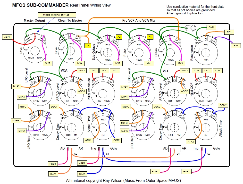
- Note the changes to the panel wiring around the mixer pots in the panel wiring diagram.
R37 and R38 removed and no longer used.
R16 and R22 removed and no longer used.
SUB-COMMANDER Guitar Synthesizer PCB Parts Layout (Parts Side Shown) PDF
I have shown (in green) some convenient ground points if you desire to run twisted pair or coax for the MX1, MX2, MX3, MX4 and or INPUT connections. The connection near the INPUT connection is actually the leads of R6 and R12.
SUB-COMMANDER Guitar Synthesizer PCB Parts Layout (Values Shown) [HUGE VALUE VIEW]
SUB-COMMANDER Guitar Synthesizer PCB Bottom Copper (Parts Side Shown)
| This image needs to be scaled so that DIP pad centers are spaced 1/10" apart (and 3/10" apart for pins across from one another). Consult your graphics aware friend for how to do that if you need to. |
SUB-COMMANDER Guitar Synthesizer PCB Top Copper(Parts Side Shown)
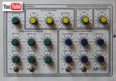
SUB-COMMANDER Guitar Synthesizer Front Panel [Front Plate PDF] [Rear Plate PDF]
| I recommend using an aluminum panel so that it can be attached to ground and thus ground all of the pot bodies. |
MFOS SUBCOMMANDER Rear Panel Wiring View PDF
Some changed have been made to the SUB-COMMANDER's mixer. The original panel drawing is here. The original panel PDF is here.
- Notice that the circuit points GTA1 and GTA2 are connected together on the schematic and also connected together on the PC board. Thus you will only see a connection from the panel to the PC board for GTA1 in the MFOS SUBCOMMANDER Rear Panel Wiring View below.
- Notice that the circuit points RDA1 and RDA2 are connected together on the schematic and also connected together on the PC board. Thus you will only see a connection from the panel to the PC board for RDA1 in the MFOS SUBCOMMANDER Rear Panel Wiring View below.
SUB-COMMANDER Guitar Synthesizer Project Parts List
LM13700 16 pin DIP Equivalents:
| Mouser | 513-NJM#13600D NJM13600D DIP-16 Dual Operational Transconductance |
| CoolAudio | V13700D DIL-16 |
*** Dual Inline Package (plastic or ceramic)
Unused designators: C44, R37, R38, R16, R22, C28, C31
| Qty. | Description | Value | Designators |
|---|---|---|---|
| 2 | LM13700 Dual gm Op Amp | LM13700 *** | U11, U13 |
| 1 | LMC555 CMOS Timer | LMC555 *** | U5 |
| 8 | TL072 Dual Op Amp | TL072 *** | U4, U6, U8, U9, U10, U12, U14, U15 |
| 2 | TL074 Quad Op Amp | TL074 *** | U1, U2 |
| 2 | CD4013 Dual D Flip Flop | CD4013 *** | U3, U7 |
| 16 | 1N914 Sw. Diode | VALUE | D4, D2, D3, D5, D6, D1, D7, D9, D11, D8, D10, D12, D14, D16, D13, D15 |
| 4 | 2N3904 | 2N3904 | Q4, Q3, Q7, Q6 |
| 4 | 2N3906 | 2N3906 | Q1, Q2, Q5, Q8 |
| 4 | Audio Taper Potentiometer | 1M | R53, R56, R61, R64 |
| 9 | Potentiometer | 100K | R57, R65, R73, R97, R109, R113, R119, R122, R125 |
| 4 | Audio Taper Potentiometer | 100K | R43, R42, R45, R41 |
| 1 | Potentiometer | 10K | R90 |
| 1 | Trim Pot | 2K | R103 |
| 24 | Resistor 1/4 Watt 5% | 100K | R12, R19, R33, R25, R36, R7, R18, R21, R34, R50, R51, R124, R55, R54, R63, R62, R84, R86, R71, R72, R95, R96, R110, R120 |
| 12 | Resistor 1/4 Watt 5% | 10K | R3, R4, R20, R26, R32, R14, R2, R44, R70, R94, R108, R117 |
| 2 | Resistor 1/4 Watt 5% | 10M | R15, R24 |
| 1 | Resistor 1/4 Watt 5% | 120K | R46 |
| 2 | Resistor 1/4 Watt 5% | 15K | R5, R10 |
| 4 | Resistor 1/4 Watt 5% | 1K | R31, R82, R83, R81 |
| 6 | Resistor 1/4 Watt 5% | 1M | R6, R8, R11, R27, R75, R99 |
| 2 | Resistor 1/4 Watt 5% | 200K | R47, R102 |
| 7 | Resistor 1/4 Watt 5% | 20K | R35, R29, R80, R89, R77, R78, R101 |
| 1 | Resistor 1/4 Watt 5% | 22K | R88 |
| 1 | Resistor 1/4 Watt 5% | 270K | R30 |
| 3 | Resistor 1/4 Watt 5% | 2K | R40, R74, R98 |
| 1 | Resistor 1/4 Watt 5% | 2M | R28 |
| 3 | Resistor 1/4 Watt 5% | 300K | R39, R48, R49 |
| 9 | Resistor 1/4 Watt 5% | 30K | R1, R58, R66, R69, R76, R93, R100, R106, R115 |
| 2 | Resistor 1/4 Watt 5% | 33K | R9, R111 |
| 2 | Resistor 1/4 Watt 5% | 39K | R112, R121 |
| 2 | Resistor 1/4 Watt 5% | 3K | R23, R17 |
| 3 | Resistor 1/4 Watt 5% | 4.7K | R85, R87, R105 |
| 1 | Resistor 1/4 Watt 5% | 43K | R104 |
| 4 | Resistor 1/4 Watt 5% | 470 ohms | R52, R60, R114, R123 |
| 3 | Resistor 1/4 Watt 5% | 47K | R91, R68, R92 |
| 1 | Resistor 1/4 Watt 5% | 6.8K | R13 |
| 1 | Resistor 1/4 Watt 5% | 680K | R118 |
| 1 | Resistor 1/4 Watt 5% | 68K | R107 |
| 2 | Resistor 1/4 Watt 5% | 82K | R79, R116 |
| 2 | Resistor 1/4 Watt 5% | 91K | R59, R67 |
| 2 | Capacitor (film or ceramic) | .001uF | C46, C45 |
| 3 | Capacitor (film or ceramic) | .01uF | C19, C34, C36 |
| 3 | Capacitor (film or ceramic) | .022uF | C5, C3, C4 |
| 2 | Capacitor (film or ceramic) | .047uF | C17, C58 |
| 37 | Capacitor (film or ceramic) | .1uF | C8, C1, C2, C7, C10, C12, C15, C13, C11, C9, C14, C16, C22, C23, C27, C30, C38, C41, C39, C42, C40, C48, C50, C49, C51, C54, C56, C55, C57, C61, C63, C62, C64, C60, C59, C67, C66 |
| 3 | Capacitor (film or ceramic) | .22uF | C6, C65 |
| 1 | Capacitor (film or ceramic) | 220pF | C18 |
| 3 | Capacitor (film or ceramic) | 22pF | C26, C33, C47 |
| 2 | Capacitor (film or ceramic) | 100pF | C43, C52 |
| 1 | Electrolytic Capacitor | 22uF | C24 |
| 4 | Non-polarized Aluminum Capacitor | 2.2uF | C20, C21, C25, C53 |
| 2 | Tantalum Capacitor | 10uF | C29, C32 |
| 2 | Tantalum Capacitor | 3.3uF | C37, C35 |
| 4 | SPST Switch | SPST | S1, S2, S3, S4 |
| 2 | 1/4" Guitar Jacks | In and Out Jacks | |
| 18 | Control Knobs | Knobs for all pots |
Miscellaneous
- (1) 1/16" thick Aluminum plate for mounting the pots and switches.
- Assorted hardware 1" 6-32 nuts and bolts, 1/2" #8 wood screws, etc
- Knobs for potentiometers, wire, solder and typical assorted electronics hand tools.
- Volt Meter and an Amplifier (or oscilloscope) for testing and enjoying.