Ray Wilson authored this content while he was actively running MFOS as the founder and resident genius.
We retain the content because it reflects a valuable point of view representing that time and place.
Article by Ray Wilson
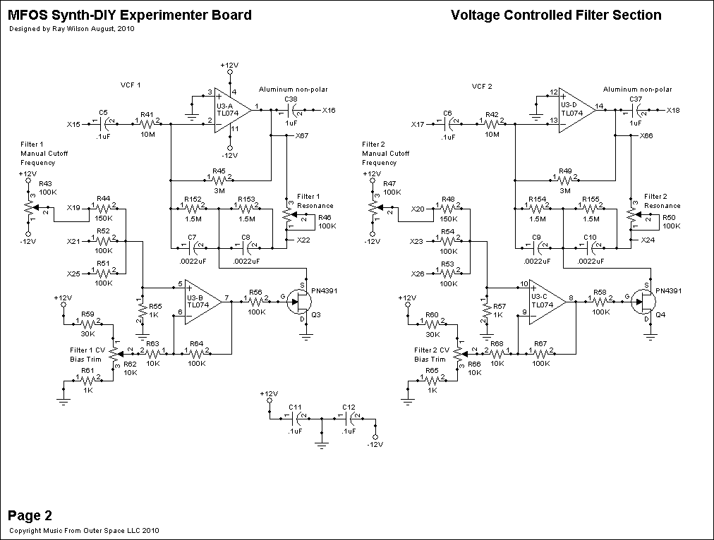
Voltage Controlled Filters Schematic (Page 2) PDF
The "Voltage Controlled Filters" are great for wah wah type effects, wind and other cool electronic sound effects. The filter's response to control voltage is approximately linear and not logarithmic. I will only describe the operation of VCF 1 located at the top of Schematic Page 2 Voltage Controlled Filter Section since VCF 2 works in exactly the same fashion. These VCF's are great for sound effect generation and work well with the high level signals from the oscillators and white noise generator. They are somewhat noisy and I do not recommend this filter design for low level signals like guitars unless the original signal is boosted sufficiently to obtain a decent signal to noise ratio.
A TL074 quad op amp U3 provides all of the op amps used in both filters. U3-A is used as the "active" element in the active low pass filter. It is essentially the low pass half of a twin T active filter. By bringing the junction of the C7 and C8 closer or further away from ground via Q3 PN4391 NFET used as a VCR (voltage controlled resistor) we change the cut off frequency of the filter. Resistors R152 and R153, 1.5M resistors, were added to lower the gain of the filter at resonance to reduce distortion. The filter is configured for a steep response curve and high overshoot (which translates to nice resonant ringing) when set for high resonance (R46 adjusted to short point X67 to point X22). When more resistance is between circuit points X67 and X22 the filter is less ringy and passes the original waveform through with less filter artifacts. R45 3M resistor stabilizes the operation of U3-A and sets the gain to 0.3 in conjunction with the 10M input resistor R41. C5 is used to block DC from the input of the filter but allows AC signals (even low frequency ones) to pass easily.
U3-B is used to level shift the expected +/-3V control voltage range to the range needed by the PN4391 NFET to operate as a VCR. The +/-3V control voltages are reduced in amplitude to about 1V peak to peak and level shifted to a range of about -8V to -7V. I found that this range gave me excellent adjustment of the filter's cut off frequency. The control voltages are mixed via 150K resistor R44 and 100K resistors R52 and R51 and dropped onto 1K resistor R55. The attenuated mixed control voltages are applied to the non-inverting input of U3-B. Resistors R59 (30K), R62 (10K trim pot) and R61 (1K) provide the biasing for U3-B. 100K resistor R64 is the feedback resistor of the control voltage mixer and R63 (10K) in conjunction with the bias network provide the gain and offset needed to supply the Q3 with the correct levels to get the widest range from the filter. R56 100K resistor limits the current being injected into Q3's gate terminal.
The filter's cutoff frequency can be adjusted manually by adjusting panel mounted R43 100K Manual Cutoff Frequency potentiometer and can be controlled from other voltage modulation sources via circuit points X21 and X25. The filter's range is about 20Hz to about 3KHz cutoff frequency.
To trim R62 set R43 (Panel mounted 100K Manual Cutoff Frequency adjust pot) to the lowest level (fully counter-clockwise) and set R46 to it's maximum setting (maximum resonance) and feed a +/-2V square wave at a frequency of about 30 Hz into the filter's input (circuit point X15). Adjust R62 so that the voltage at the output of U3-B pin 7 is -7.5V. The passed 30 Hz signal should be very low in amplitude and only the lowest frequency elements of the signal (kind of a distorted sine shape) should be observed. Now turn the filter's Manual Cutoff Frequency adjust pot up slowly to the maximum and the characteristic "wah" sound should be heard and the cut off frequency should go up significantly. I found variation between several PN4391 NFETs and changed one out in one of my filters in order to get the correct behavior. I suggest you buy a few (they should NOT be inexpensive) so you are not stuck with a “non-winner”.
C11 and C12 are used to bypass the power supply lines to this portion of the PC board.
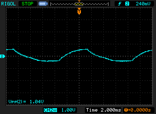
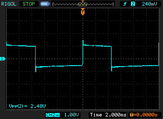
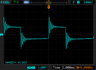
VCF Scope Photos
Oscillator 1's square wave is being fed into the filter.
| Low COF (Cut Off Frequency) | High COF low resonance. | High COF high resonance. |
|
|
|
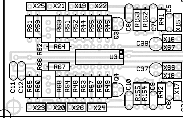
Voltage Controlled Filters PCB Section Parts Layout (Parts Side Shown)
I find this one useful for trouble shooting since the designators on the PC board are covered by the installed components.
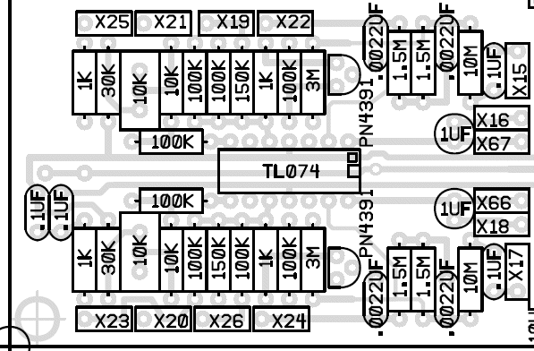
Voltage Controlled Filters PCB Section Part Value View (Parts Side Shown)
I find this one useful for populating the PC board since I don't have to continually refer back to the schematic to know the value for a designator.
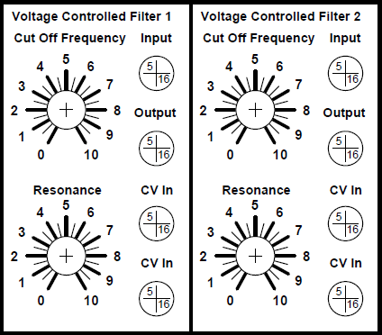
Voltage Controlled Filters Front Panel Template
These front panel layouts are suggestions and are meant to illustrate the circuit's user interface and wiring between the panel and the PC board. I'm certain you can come up with a much cooler looking panel but this utilitarian version will certainly work to get you started.
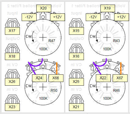
Voltage Controlled Filters Front Panel Wiring
Voltage Controlled Filters Project Parts List (See "Full Parts List" tab for Complete List)
Resistor Color Chart For Resistors Used In This Circuit
The resistors should be carbon composition or carbon film.Use 1/4 watt resistors because 1/2 watt will be too big for the board.
| Qty. | Description | Value | Designators |
|---|---|---|---|
| 1 | TL074 Quad Op Amp | TL074 | U3 |
| 2 | PN4391 NFET | PN4391 | Q3, Q4 |
| 4 | Potentiometer Linear Taper | 100K | R43, R46, R47, R50 |
| 4 | Resistor 1/4 Watt 5% | 1.5M | R152, R153, R154, R155 |
| 8 | Resistor 1/4 Watt 5% | 100K | R51, R52, R53, R54, R56, R58, R64, R67 |
| 2 | Resistor 1/4 Watt 5% | 10K | R63, R68 |
| 2 | Resistor 1/4 Watt 5% | 10M | R41, R42 |
| 2 | Resistor 1/4 Watt 5% | 150K | R44, R48 |
| 4 | Resistor 1/4 Watt 5% | 1K | R55, R57, R61, R65 |
| 2 | Resistor 1/4 Watt 5% | 30K | R59, R60 |
| 2 | Resistor 1/4 Watt 5% | 3M | R45, R49 |
| 2 | Trim Pot | 10K | R62, R66 |
| 2 | Capacitor Alum. Nonpolarized (small w/radial leads) | 1uF | C37, C38 |
| 4 | Capacitor Ceramic | .0022uF | C7, C8, C9, C10 |
| 4 | Capacitor Ceramic | .1uF | C5, C6, C11, C12 |
Miscellaneous
- 1/16" thick aluminum plate for mounting the pots and switches.
- Assorted hardware 1" 6-32 nuts and bolts, 1/2" #8 wood screws, etc
- Knobs for potentiometers, wire, solder and typical assorted electronics hand tools.
- Digital volt meter and a signal tracer or oscilloscope for testing.