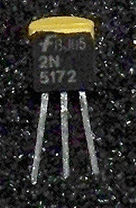
2N5172 Selected NPN Noise Transistor
To purchase click the white cart icon in the upper right corner.
Description
These 2N5172 NPN transistors have been tested and selected for their emitter base reverse bias noise.
They give greater than 3V peak to peak noise with a non-inverting gain of 100. While testing I observed
a wide range of noise levels with > 3V p-p as what I consider the lowest acceptable level. However several of the
tested transistors caused clipping at a gain of 100 because they are very noisy. Due to this fact it is often necessary to
reduce the gain in the white noise generation section of many MFOS circuits when using one of these selected 2N5172
noise transistors. Below you will find information for several MFOS projects regarding which component(s) to adjust the value of to
reduce the noise signal gain if necessary.
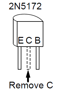
Notice the pinout of the 2N5172 (ECB, remove the middle C lead) and be sure to install it correctly into your board. The 2N5172 pinout when viewing the flat side with pins down is ECB. You may be replacing a 2N3904 whose pinout when viewing the flat side with pins down is EBC.
See the 2N5172 data sheet for complete specs.
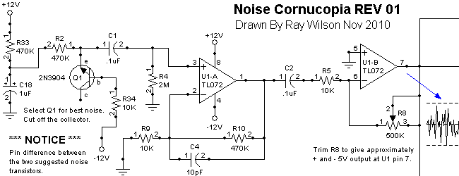
Adjusting Noise Cornucopia Rev 01 White Noise Gain
As can be seen the first stage gain of U1-A is about 48 and the next stage allows trimming of the gain. However a really noisy transistor may cause clipping in the first stage so if you need to reduce the gain lower the value of R10 or increase the value of R9. Gain = (R10 Value)/(R9 Value) + 1. Adjust R8 noise trim as necessary to achieve the correct p-p level out of U1-B (about 10V p-p).
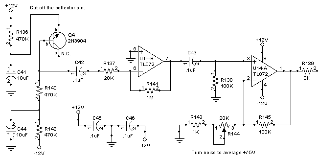
Adjusting Sound Lab ULTIMATE White Noise Gain
As can be seen the first stage gain of U14-B is about -50 and the next stage allows trimming of the gain. However a really noisy transistor may cause clipping in the first stage so if you need to reduce the gain increase the value of R137. Gain = -(R141 Value)/(R137 Value). Adjust R144 noise trim as necessary to achieve the correct p-p level out of U1-B (about 10V p-p).
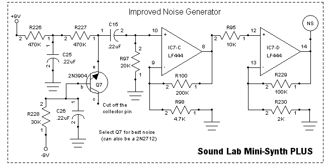
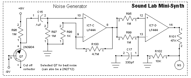
Adjusting Sound Lab Mini-Synth White Noise Gain
The Sound Lab Mini-Synth's noise generator is a bit different from the other noise generators in that it really gains up the first stage with a whopping gain of 4701. The second stage is designed to then use whatever noise signal it gets from the first stage and practically turn it into digital noise with it's comparator scheme. I don't think it is necessary to use one of these selected noise transistors in this circuit. Of course if you needed to reduce the gain of the first stage I suggest you decrease the value of R100.
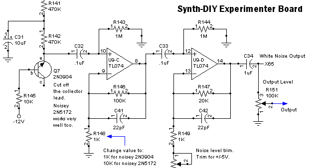
Adjusting Synth-DIY Experimenter White Noise Gain
As can be seen the first stage gain of U9-C is about 101 and the next stage allows trimming of the gain. However a really noisy transistor may cause clipping in the first stage so if you need to reduce the gain reduce the value of R146 or increase the value of R148. Gain = (R146 Value)/(R148 Value) + 1. Adjust R150 noise trim as necessary to achieve the correct p-p level out of U9-D (about 10V p-p).
Adjusting Sound Lab Mini-Synth PLUS White Noise Gain
As can be seen the first stage gain of IC7-C is about 43 and the next stage adds another multiple of 10 to the gain. However a really noisy transistor may cause clipping in the first stage so if you need to reduce the gain reduce the value of R100 or increase the value of R98. Gain = (R100 Value)/(R98 Value) + 1. Adjust R229 IC7-D feedback resistor as necessary to achieve the correct p-p level out of U9-D (about 10V p-p).